EE-SPX403-N Omron, EE-SPX403-N Datasheet
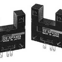
EE-SPX403-N
Specifications of EE-SPX403-N


Related parts for EE-SPX403-N


EE-SPX403-N Summary of contents
Page 1
... H with a Light-ON indicator Wide operating voltage range ( VDC) makes smooth connection possible with TTLs, relays, and programmable controllers (PLC) Convert to PNP output with EE-2002 H conversion connector EE-SPX303-1 model is available for H applications that require a 5 VDC input Ordering Information Appearance Sensing method Slot width Slot depth ...
Page 2
... Indicator Without detecting object (S (See note 1 With detecting object Response frequency (See note 2.) Light source Receiver Connecting method Note: 1. The indicator is a GaP red LED (peak emission wave- length: 700 nm). 2. The response frequency was measured by detecting the following disks rotating. ...
Page 3
... Engineering Data J SENSING POSITION CHARACTERISTICS (EE-SPX303) Dark-ON mode OFF Distance d (mm) Note: The sensing position characteristics of the EE-SPX403 are opposite those of the EE-SPX303. Operation J INTERNAL/EXTERNAL CIRCUIT DIAGRAM Light-ON/Dark- VDC Operation indicator 1.5 to Load 3 mA (relay) OUT Main ← I circuit C Logic circuit Connect a diode in parallel to the load when an inductive load is connected between + and OUT ...
Page 4
... J EE-SPX303 (403) + EE-1001 0.6 (0.02) 2.9±1 J EE-SPX303 (403) + EE-1006 25 15 Terminal Arrangement (0.98) (0.59) Red (Brown) (1) Yellow (Pink) (2) (3) White (Black) Black (Blue) (4) IEC colors are shown in parentheses. 7.4 (0.29) ...
Page 5
... A cable with a thickness of AWG24 min. and a length max. must be connected to the output terminals. To use a cable longer than 5 m, attach a capacitor with a capacitance of approximately 10 µF to the wires, as shown below. The distance between the terminal and the capacitor must be within VDC (5 VDC for EE-SPX303-1) ...