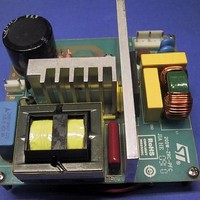
EVL6563S-200ZRC STMicroelectronics, EVL6563S-200ZRC Datasheet - Page 29

EVL6563S-200ZRC
Manufacturer Part Number
EVL6563S-200ZRC
Description
Power Management Modules & Development Tools Tranisition Mode PFC L6563S EVL Board
Manufacturer
STMicroelectronics
Type
Motor / Motion Controllers & Driversr
Datasheet
1.EVL6563S-200ZRC.pdf
(39 pages)
Specifications of EVL6563S-200ZRC
Product
Power Management Modules
Lead Free Status / RoHS Status
Lead free / RoHS Compliant
AN3180
Appendix A
A system of coupled inductors is a set of coils that share one or more common magnetic
paths because of their proximity. Because of this, magnetic flux changes in any one coil do
not only induce a voltage across that coil by self-induction, but also across the others by
mutual induction.
Accurate descriptions of coupled inductors use the reluctance model approach and its
derivations, which closely represent the physical structure of the magnetic element. This
approach is especially useful when dealing with complex magnetic structures, which is not
the case under consideration. Here a simpler method is used based on the terminal
equations describing the electrical behavior of the magnetic structure.
From an electrical standpoint, a system of m coupled inductors, is defined by m coefficients
of self-inductance, relating the voltage across any inductor to the rate of change of current
through the same inductor, and m·(m-1) coefficients of mutual inductance, equal in two by
two, relating the voltage induced across any inductor to the rate of change of current in
every other inductor.
Considering the important practical case of coupled inductors wound on the same core of
magnetic material, each inductor is commonly termed “winding”. Focusing on the case m=2,
a system of two coupled inductors, which are designated as the primary and the secondary
winding, is a linear, time-independent two-port circuit described by the following branch-
constitutive equations:
Equation 21
where L1 and L2 are the self-inductances of the primary and the secondary windings
respectively, and M is the mutual inductance. Winding resistance is assumed to be
negligible.
Unlike L1 and L2, which are inherently positive, M can be either positive or negative,
depending on the voltage polarity of the windings relative to one another: a positive rate of
change of the current in one winding can induce a voltage either positive or negative in the
other winding. As shown in
important rules:
1.
2.
3.
Based on rule 1 and on the sign convention of the terminal voltages and currents of two-port
circuits, it is easy to see that for the coupled inductors in
those on the right M<0.
Voltages induced in any winding due to mutual flux changes have the same polarity at
dotted terminals
Positive currents flowing into the dotted terminals produce aiding magneto-motive
forces
If one winding is open circuited and the current flowing into the dotted terminal of the
other winding has a positive rate of change, the voltage induced in the open winding is
positive at the dotted terminal.
Electrical equivalent circuit models of coupled inductors and transformers
Electrical equivalent circuit models of
coupled inductors and transformers
Figure 23
Doc ID 17273 Rev 1
v
v
1
2
(t)
(t)
, this is indicated by dot notation, which follows three
=
L
M
1
L
M
2
dt
d
i
i
1
2
(t)
(t)
Figure 23
on the left M>0, while for
29/39


