PIC-GSM Olimex Ltd., PIC-GSM Datasheet - Page 24
PIC-GSM
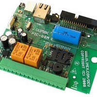
Manufacturer Part Number
PIC-GSM
Description
MCU, MPU & DSP Development Tools DEV BRD W/GSM MOD PIC18F97J60-I/PT
Manufacturer
Olimex Ltd.
Datasheet
1.PIC-GSM.pdf
(26 pages)
Specifications of PIC-GSM
Processor To Be Evaluated
PIC18F67J50
Data Bus Width
8 bit
Interface Type
Ethernet, USB, I2C, SPI, UART
Dimensions
100 mm x 80 mm
Operating Supply Voltage
5 V
Tool Type
Development Kit
Core Architecture
PIC
Cpu Core
PIC
Lead Free Status / RoHS Status
Lead free / RoHS Compliant
Other names
1772148 51R7061


Advices to customer for further use:
•
•
•
•
•
Log “1” of Relay1 (PG7) and Relay2 (PG6) outputs means that the Relay is turned on,
while log “0” mean that the Relay is turned off.
Log “1” to the LED output (PG5) means that LED is turned off, while log “0” mean
that the LED is turned on.
Logical “1” on Opto input 1(RG3) and Opto input 2 (RG4) means that high voltage is
applied to the input
Status page item “seconds” displays seconds elapsed from program start, measured
by RTC.
Status page item “Uin” displays input voltage in Volts, measured on RA5(AN4) pin .
“Test board area” section is not intended for user examination and shouldn't be used
by customer.
User should be familiar with basic AT commands(make call, send SMS, read SMS
etc).
SIM card, you put should be with disabled PIN code use. So before use, put SIM card
in normal GSM and disable PIN code use.
Related parts for PIC-GSM
Image
Part Number
Description
Manufacturer
Datasheet
Request
R

Part Number:
Description:
MCU, MPU & DSP Development Tools MPLAB 8/18/28/40P FOR PICSTART+
Manufacturer:
Olimex Ltd.

Part Number:
Description:
MCU, MPU & DSP Development Tools DEV BRD FOR 28 PIN MICRO CONT
Manufacturer:
Olimex Ltd.
Datasheet:

Part Number:
Description:
MCU, MPU & DSP Development Tools PROTOTYPE BRD FOR 40 PIN PIC
Manufacturer:
Olimex Ltd.
Datasheet:

Part Number:
Description:
MCU, MPU & DSP Development Tools PROTOTYPE BRD ICSP/ ICD ENABLED 28 PIN
Manufacturer:
Olimex Ltd.
Datasheet:

Part Number:
Description:
MCU, MPU & DSP Development Tools PROTOTYPE BRD ICSP/ ICD ENABLED 14 PIN
Manufacturer:
Olimex Ltd.
Datasheet:

Part Number:
Description:
MCU, MPU & DSP Development Tools PROTOTYPE BRD FOR 28 PIN PIC
Manufacturer:
Olimex Ltd.
Datasheet:

Part Number:
Description:
Development Boards & Kits - PIC / DSPIC MINI PROTOTYPE BRD FOR 8 PIN PIC
Manufacturer:
Olimex Ltd.

Part Number:
Description:
MCU, MPU & DSP Development Tools TCP-IP DEV BRD FOR PIC18F67J60
Manufacturer:
Olimex Ltd.
Datasheet:

Part Number:
Description:
MCU, MPU & DSP Development Tools PROTOTYPE BRD ICSP/ ICD ENABLED 40 PIN
Manufacturer:
Olimex Ltd.
Datasheet:

Part Number:
Description:
MCU, MPU & DSP Development Tools PROTOTYPE BRD FOR PIC18F67J60
Manufacturer:
Olimex Ltd.
Datasheet:

Part Number:
Description:
Microcontroller & Microprocessor Development Tools TCP-IP DEV BRD PIC32MX460F512
Manufacturer:
Olimex Ltd.
Datasheet:

Part Number:
Description:
Microcontroller & Microprocessor Development Tools PROTOTYPE BOARD TMS320F28027
Manufacturer:
Olimex Ltd.
Datasheet:

Part Number:
Description:
Microcontroller & Microprocessor Development Tools HDR BRD FOR LPC3131
Manufacturer:
Olimex Ltd.
Datasheet:

Part Number:
Description:
Microcontroller & Microprocessor Development Tools MP3 PLYR MOD WITH VS1002
Manufacturer:
Olimex Ltd.
Datasheet:
Part Number:
Description:
Microcontroller & Microprocessor Development Tools MP3 PLYR MOD BAT WITH VS1002
Manufacturer:
Olimex Ltd.
Datasheet: