PIC-LCD3310 Olimex Ltd., PIC-LCD3310 Datasheet
PIC-LCD3310
Specifications of PIC-LCD3310
Available stocks


Related parts for PIC-LCD3310


PIC-LCD3310 Summary of contents
Page 1
... PIC-LCD-3310 development board Copyright(c) 2011, OLIMEX Ltd, All rights reserved Users Manual Rev.B, January 2011 Page 1 ...
Page 2
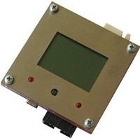
... PCB: FR-4, 1.5 mm (0,062''), soldermask, silkscreen component print Dimensions 65x65 mm (2.56 x 2.56") ELECTROSTATIC WARNING: The PIC-LCD3310 board is shipped in protective anti-static packaging. The board must not be subject to high electrostatic potentials. General practice for working with static sensitive devices should be applied when working with this board. ...
Page 3
MPLAB ICD 2, wait while MPLAB is downloading operation system, and after ICD2 is connected – check in menu Programmer – Settings – Power – there is option – Power target circuit from MPLAB ICD 2 – this ...
Page 4
... PROCESSOR FEATURES: PIC-LCD3310 board use MCU PIC18F67J50 from Microchip with these features: USB V2.0 Compliant SIE - Low Speed (1.5 Mb/s) and Full Speed (12 Mb/s) - Supports Control, Interrupt, Isochronous and - Bulk Transfers Supports Endpoints (16 bidirectional) - Supports Endpoints (16 bidirectional) - 3.9-Kbyte Dual Access RAM for USB ...
Page 5
Idle: CPU off, peripherals on o Sleep: CPU off, peripherals off o Priority Levels for Interrupts - Self-Programmable under Software Control - Single-Cycle Hardware Multiplier - Extended Watchdog Timer (WDT): - Programmable period from ...
Page 6
BLOCK DIAGRAM: Page 6 ...
Page 7
MEMORY MAP: Page 7 ...
Page 8
SCHEMATIC: + 33k/5% R24 33k/5% R23 33k/5% R22 33k/5% R21 33k/5% R20 2 Page 8 MINI_USB USB GND2 GND4 USB GND1 GND3 1 + ...
Page 9
... BOARD LAYOUT: POWER SUPPLY CIRCUIT: PIC-LCD-3310 takes power from a battery +(4.5-6)VDC or from the mini USB port. The board power consumption at 5-6VDC the consumption is about 20mA. RESET CIRCUIT: PIC-LCD-3310 doesn't have reset circuit. The MCU resets if you apply logical zero (GND) to EXT1.pin ICSP.pin 1. ...
Page 10
... Timer1 which could function as a Real Time Clock. JUMPER DESCRIPTION: 3.3V_E enables 3.3 V power supply for the PIC18F67J50 and all other devices INPUT/OUTPUT: Status red LED with name LED1 connected to PIC18F67J50 pin 64 (RE2/PMBE/P2B). Status red LED with name LED2 connected to PIC18F67J50 pin 63 (RE3/PMA13/P3C/REFO). Joystick with name J1 and with five positions – ...
Page 11
EXT1: Pin # 1 +3.3V 3 +5V 5 BAT_SENS 7 RB3 9 RB7/PGD 11 RG1 13 RG3 15 RST BAT_SENS Input Battery Power Supply. This signal tells the processor that it is powered by the battery. I/O Program Data. Serial ...
Page 12
EXT2: Pin # 1 +3.3V 3 +5V 5 RC2 7 RC7/RX1 9 RE3/LED2 11 USB_SENS RE7 13 15 RF5 TX1 Output Transmit Data 1. This is the output data line for the UART1. Input Receive Data 1. This is the ...
Page 13
UEXT: Pin # 1 +3.3V 2 GND 3 RC6/TX1 4 RC7/RX1 5 SCK2/SCL2 6 MISO2/SDA2 7 MISO1 8 MOSI1 9 SCK1 10 RE4/CS_UEXT TX1 Output Transmit Data 1. This is the output data line for the UART1. Input Receive Data ...
Page 14
BAT: Pin # 1 +(4.5-6.0)VDC 2 GND Mini USB: Pin # 1 + GND D- and D+ both form differential input or output depending on the direction of the data flow. Signal Name ...
Page 15
SD/MMC card slot: Pin # 1 #SS2 3 GND 5 SCK2/SCL2 7 MISO2/SDA2 9 +3. GND Output Slave Select 2. This signal is Slave Select for the SPI2 interface. As the MSU is #SS2 master, ...
Page 16
Page 16 ...
Page 17
... AVAILABLE DEMO SOFTWARE : Test demo code – GPS compass – You could find information about PIC-LCD-3310 demo software at www.olimex.com/dev (C source and HEX) with MOD-GPS and PIC-LCD3310 (C source and HEX) . Page 17 ...
Page 18
... ORDER CODE: PIC-LCD-3310 – assembled and tested (no kit, no soldering required) How to order? You can order to us directly or by any of our distributors. Check our web All boards produced by Olimex are RoHS compliant Revision history: REV.A REV. B www.olimex.com/dev for more info. - created July 2008 - created January 2011 – ...
Page 19
... However all warranties implied or expressed including but not limited to implied warranties of merchantability or fitness for purpose are excluded. This document is intended only to assist the reader in the use of the product. OLIMEX Ltd. shall not be liable for any loss or damage arising from the use of any information in this document or any error or omission in such information or any incorrect use of the product ...