PIC-P18-20MHz Olimex Ltd., PIC-P18-20MHz Datasheet - Page 6
PIC-P18-20MHz
Manufacturer Part Number
PIC-P18-20MHz
Description
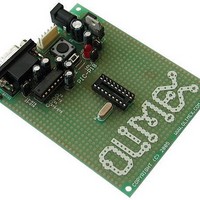
MCU, MPU & DSP Development Tools PROTOTYPE BRD FOR 18 PIN PIC
Manufacturer
Olimex Ltd.
Datasheet
1.PIC-P18-20MHZ.pdf
(8 pages)
Specifications of PIC-P18-20MHz
Processor To Be Evaluated
18 Pin PIC Devices
Interface Type
RS-232, ICSP
Dimensions
100 mm x 80 mm
Operating Supply Voltage
3.3 V, 5 V
Lead Free Status / RoHS Status
Lead free / RoHS Compliant


SOFTWARE:
DEMO1:
DEMO2:
DEMO3:
This is demo code which blinks the LED on PIC-P18 board.
Note:
This is demo code which show how to read BUTTON status and to switch
the LED ON when button is pressed and LED off when the button is
depressed.
This is demo code, which show how to use the USART to send and receive
characters from host PC via RS232 cable.
The MAX232 by default is not connected to PIC on the board so you have to
solder two wires – one from RB2 (pin #8) of PIC16F628 Tx signal to MAX232
Rx labeled pin, and second from RB1 (pin #7) of PIC16F628 Rx signal to
MAX232 Tx labeled pin.
IMPORTANT: as seen from the schematic RB2 is also connected to the
User button, this means if you press the button during the
communication the communication will be lost and you may burn your
PIC UART port!
You must program the HEX code to PIC16F628 and run the code.
If you programmed the PIC correctly and wired the UART, when you open
Hyperterminal on your host PC computer with 9600 bps, 8 data bit, 1 stop
bit, No flow control and apply power supply to the PIC-P18 every character
you type on the hyperterminal will be printed back with “*” i.e. if you type
“abc” you will receive “a*b*c*”.
PIC16F628-I/P
PIC16F628-I/P
PIC16F628-I/P
LED jumper should be closed!
BLINK LED
BUTTON read
RS232 send / receive routines
Page 6
Related parts for PIC-P18-20MHz
Image
Part Number
Description
Manufacturer
Datasheet
Request
R

Part Number:
Description:
DEVELOPMENT BOARD FOR 18 PIN PIC MICROCONTROLLERS
Manufacturer:
Olimex Ltd.
Datasheet:

Part Number:
Description:
IC MCU OTP 2KX12 28DIP
Manufacturer:
Microchip Technology
Datasheet:

Part Number:
Description:
IC PIC MCU 8BIT 14KB FLSH 14PDIP
Manufacturer:
Microchip Technology
Datasheet:

Part Number:
Description:
IC MCU OTP 2KX16 PWM 40DIP
Manufacturer:
Microchip Technology
Datasheet:

Part Number:
Description:
IC MCU OTP 512X14 COMP 18DIP
Manufacturer:
Microchip Technology
Datasheet:
Part Number:
Description:
IC MCU OTP 2KX14 A/D PWM 18DIP
Manufacturer:
Microchip Technology
Datasheet:
Part Number:
Description:
IC MCU OTP 2KX12 18DIP
Manufacturer:
Microchip Technology
Datasheet:
Part Number:
Description:
IC MCU OTP 1KX14 COMP 18DIP
Manufacturer:
Microchip Technology
Datasheet:
Part Number:
Description:
IC MCU OTP 1KX14 COMP 18DIP
Manufacturer:
Microchip Technology
Datasheet:
Part Number:
Description:
IC MCU OTP 512X12 18DIP
Manufacturer:
Microchip Technology
Datasheet:
Part Number:
Description:
IC MCU OTP 512X12 18DIP
Manufacturer:
Microchip Technology
Datasheet:
Part Number:
Description:
IC MCU OTP 4KX14 COMP 40DIP
Manufacturer:
Microchip Technology
Datasheet:
Part Number:
Description:
IC MCU OTP 2KX14 A/D PWM 18DIP
Manufacturer:
Microchip Technology
Datasheet:
Part Number:
Description:
IC MCU OTP 2KX14 A/D PWM 18DIP
Manufacturer:
Microchip Technology
Datasheet:
Part Number:
Description:
IC MCU OTP 512X12 28DIP
Manufacturer:
Microchip Technology
Datasheet: