28230 Parallax Inc, 28230 Datasheet - Page 4
28230
Manufacturer Part Number
28230
Description
MCU, MPU & DSP Development Tools Propeller Dev Board (MSR1)
Manufacturer
Parallax Inc
Datasheet
1.28230.pdf
(9 pages)
Specifications of 28230
Processor To Be Evaluated
P8X32A-Q44
Interface Type
USB
Dimensions
77.5 cm x 102.9 cm x 13.4 cm
Maximum Operating Temperature
+ 70 C
Operating Supply Voltage
6.5 to 15 V
Lead Free Status / RoHS Status
Lead free / RoHS Compliant
Available stocks
Company
Part Number
Manufacturer
Quantity
Price
Company:

Part Number:
28230-60-01
Manufacturer:
ORN
Quantity:
25
Company:
Part Number:
28230-910-01
Manufacturer:
ORN
Quantity:
20


The L6205 inputs are connected to P24 through P27 on the Propeller chip. When the power switch on the
control board is set for POWER ON/MOTORS ON, the L6205 is enabled and the outputs are connected to the
motors. The truth table for controlling the L6205 is shown below in Table 1. P24 and P25 control Motor A
while P26 and P27 control Motor B. This table assumes the motors are connected to the control board such
that the left motor is connected to the Motor A connection and the right motor is connected to the Motor B
connection. Polarity should be the same on both connectors. The motor polarity may need to be reversed
to match the table, depending on the motor.
Note that it may be more intuitive to look at the table as two groups consisting of P24/P25 and P26/P27. In
this manner you have 4 possible combinations for each motor as shown in Table 2.
Pulse-width modulating one of the inputs in the opposite state of the other pin will cause that motor to move
at a speed proportional to the duty cycle of the signal. A wide range of frequencies could be used for pulse-
width modulating DC brushed motors.
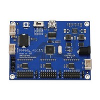
The USB Serial Interface (P30 – P31)
The USB interface (see the figure at right) provides a serial connection to the
Propeller chip through the USB port of your PC. This interface is used for both
programming and communication with the control board and is based on the FTDI
FT232RL. A green LED indicates data coming into the control board and a red LED
indicates data being sent to the PC. Data coming into the control board goes to P31
on the Propeller chip while data being sent comes from P30.
Copyright © Parallax Inc.
P24
P24
0
1
0
1
0
1
0
1
0
1
0
1
0
1
0
1
0
1
0
1
P25
P25
0
0
1
1
0
0
1
1
0
0
1
1
0
0
1
1
0
0
1
1
P26
0
0
0
0
1
1
1
1
0
0
0
0
1
1
1
1
Left Motor
Propeller Robot Control Board (#28230)
Reverse
Forward
Brake
Brake
Table 1: Motor Truth Table
P27
0
0
0
0
0
0
0
0
1
1
1
1
1
1
1
1
Table 2
P26
Left Motor
0
1
0
1
Reverse
Reverse
Reverse
Reverse
Forward
Forward
Forward
Forward
Brake
Brake
Brake
Brake
Brake
Brake
Brake
Brake
P27
0
0
1
1
v1.0 11/3/2009 Page 4 of 9
Right Motor
Right Motor
2
Reverse
Reverse
Reverse
Reverse
Forward
Forward
Forward
Forward
Forward
Reverse
Brake
Brake
Brake
Brake
Brake
Brake
Brake
Brake
Brake
Brake
7
Related parts for 28230
Image
Part Number
Description
Manufacturer
Datasheet
Request
R


Part Number:
Description:
Microcontroller Modules & Accessories DISCONTINUED BY PARALLAX
Manufacturer:
Parallax Inc

Part Number:
Description:
BOOK UNDERSTANDING SIGNALS
Manufacturer:
Parallax Inc
Datasheet:


Part Number:
Description:
COMPETITION RING FOR SUMOBOT
Manufacturer:
Parallax Inc
Datasheet:


Part Number:
Description:
TEXT INFRARED REMOTE FOR BOE-BOT
Manufacturer:
Parallax Inc
Datasheet:
Part Number:
Description:
BOARD EXPERIMENT+LCD NX-1000
Manufacturer:
Parallax Inc
Datasheet:

Part Number:
Description:
CONTROLLER 16SERVO MOTOR CONTROL
Manufacturer:
Parallax Inc
Datasheet:

Part Number:
Description:
BASIC STAMP LOGIC ANALYZER
Manufacturer:
Parallax Inc
Datasheet:

Part Number:
Description:
IC MCU 2K FLASH 50MHZ SO-18
Manufacturer:
Parallax Inc
Datasheet: