AVR-GSM Olimex Ltd., AVR-GSM Datasheet - Page 18
AVR-GSM
Manufacturer Part Number
AVR-GSM
Description
MCU, MPU & DSP Development Tools DEV BRD FOR ATMEGA32 32KB FLASH 2KB RAM
Manufacturer
Olimex Ltd.
Datasheet
1.AVR-GSM.pdf
(22 pages)
Specifications of AVR-GSM
Processor To Be Evaluated
ATMega32
Data Bus Width
8 bit
Interface Type
USB, SPI, UART
Dimensions
130 mm x 82 mm
Operating Supply Voltage
12 V
Tool Type
Development Kit
Core Architecture
AVR
Cpu Core
AVR 8
Silicon Manufacturer
Atmel
Silicon Core Number
ATmega32
Kit Contents
Board
Features
USB Interface, On-Board Temperature Digital Sensor
Rohs Compliant
Yes
Lead Free Status / RoHS Status
Lead free / RoHS Compliant
Other names
1776311 52R3434


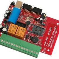
INPUT/OUTPUT:
Button B1: user button connected to ATmega32 pin.12 PD3 (INT1);
PWRKEY button – This is GSM module power on/off key. When the module
is ON if you press and hold for more than 3 seconds the module go in
power down state. If the module if in power down mode and you press and
hold this key for more than 1 second the module will go in ON mode.
MIC – on-board microphone (voice), with AT command you can switch the
voice audio input to be taken from this microphone of from the handsfree
audio connector.
SPEAKER – voice output for external 32 ohm speaker, with AT command
you can switch the voice audio output to be directed to this speaker or to
the handsfree audio connector.
HANDSFREE – audio 2.5 mm jack voice input and speaker output.
BUZ – audio buzzer , can be used as RING signalization.
Status green LED with name LED connected to ATmega32 pin.16 PD7.
Status red LED with name STAT – indicates the state of GSM module.
STAT is off state – GSM module is not running
64ms On/ 800ms Off – GSM module does not find the network
64ms On/ 3000ms Off – GSM module is connected to the network
64ms On/ 300ms Off - GPRS communication
Optocouple 1 – OPT1 (H11A817SMD) - 5V-12V optoisolated input with
LED2 indication and open collector output connect to ATMega32 pin.40
(PB0(T0)). Positive voltage of '+' terminal and negative voltage or GND of '-'
terminal of OPT_TEMP connector, reflect with log. 0 of Mega32 input.
Optocouple 2 – OPT2 (H11A817SMD) - 5V-12V optoisolated input with
LED3 indication and open collector output connect to ATMega32 pin.11
(PD2(INT0)).Positive voltage of '+' terminal and negative voltage or GND of '-'
terminal of OPT_TEMP connector, reflect with log. 0 of Mega32 input.
Relay1 – REL1 240VAC/10A (RAS1215) with default tied Normal Close (NC)
and COM terminals and disconnected Normal Open and COM terminals.
LED_R1 (Red) indicated when turn on REL1. The relay is turned on with
log 1 of PC7 port.
Relay1 – REL2 240VAC/10A (RAS1215) with default tied Normal Close (NC)
and COM terminals and disconnected Normal Open and COM terminals.
LED_R2 (Red) indicated when turn on REL2. The relay is turned on with
log 1 of PC6 port.
Page 18
Related parts for AVR-GSM
Image
Part Number
Description
Manufacturer
Datasheet
Request
R

Part Number:
Description:
MCU, MPU & DSP Development Tools PROTOTYPE BRD FOR STK200 20PIN
Manufacturer:
Olimex Ltd.
Datasheet:

Part Number:
Description:
MCU, MPU & DSP Development Tools PROTOTYPE BRD FOR STK200 28PIN
Manufacturer:
Olimex Ltd.
Datasheet:

Part Number:
Description:
MCU, MPU & DSP Development Tools PROTOTYPE BRD FOR STK200 10PIN
Manufacturer:
Olimex Ltd.
Datasheet:

Part Number:
Description:
Programmers & Debuggers AVR PROGRAMMER 2MB FLASH
Manufacturer:
Olimex Ltd.
Datasheet:

Part Number:
Description:
MCU, MPU & DSP Development Tools PROTOTYPE BRD FOR AT90USB162
Manufacturer:
Olimex Ltd.
Datasheet:

Part Number:
Description:
Programmers & Debuggers AVR PROGRAMMER 2MB FLASH 1000V
Manufacturer:
Olimex Ltd.
Datasheet:

Part Number:
Description:
Programmers & Debuggers USB AVR PROGRAMMER
Manufacturer:
Olimex Ltd.
Datasheet:

Part Number:
Description:
MCU, MPU & DSP Development Tools DEV BRD FOR AT90CAN128
Manufacturer:
Olimex Ltd.
Datasheet:

Part Number:
Description:
MCU, MPU & DSP Development Tools HDR BRD FOR AT90CAN128-16AU
Manufacturer:
Olimex Ltd.
Datasheet:

Part Number:
Description:
MCU, MPU & DSP Development Tools DEV BRD FOR AT90USB162
Manufacturer:
Olimex Ltd.
Datasheet:

Part Number:
Description:
Microcontroller & Microprocessor Development Tools TCP-IP DEV BRD PIC32MX460F512
Manufacturer:
Olimex Ltd.
Datasheet:

Part Number:
Description:
Microcontroller & Microprocessor Development Tools PROTOTYPE BOARD TMS320F28027
Manufacturer:
Olimex Ltd.
Datasheet:

Part Number:
Description:
Microcontroller & Microprocessor Development Tools HDR BRD FOR LPC3131
Manufacturer:
Olimex Ltd.
Datasheet:

Part Number:
Description:
Microcontroller & Microprocessor Development Tools MP3 PLYR MOD WITH VS1002
Manufacturer:
Olimex Ltd.
Datasheet:
Part Number:
Description:
Microcontroller & Microprocessor Development Tools MP3 PLYR MOD BAT WITH VS1002
Manufacturer:
Olimex Ltd.
Datasheet: