AT90USBKEY Atmel, AT90USBKEY Datasheet
AT90USBKEY
Specifications of AT90USBKEY


Related parts for AT90USBKEY


AT90USBKEY Summary of contents
Page 1
... AT90USBKey ............................................................................................. Hardware User Guide ...
Page 2
... AT90USBKey Hardware User Guide User Guide Section 1 Introduction ........................................................................................... 1-3 1.1 Overview ...................................................................................................1-3 1.2 AT90USBKey Features............................................................................1-4 Section 2 Using the AT90USBKey ....................................................................... 2-5 2.1 Overview ...................................................................................................2-5 2.2 Power Supply ............................................................................................2-6 2.3 Reset.........................................................................................................2-8 2.4 On-board Resources.................................................................................2-9 2.5 In-System Programming .........................................................................2-13 2.6 Debugging...............................................................................................2-14 Section 3 Troubleshooting Guide ...
Page 3
... Overview AT90USBKey Hardware User Guide Congratulations on acquiring the AVR® AT90USBKey. This kit is designed to give designers a quick start to develop code on the AVR® and for prototyping and testing of new designs with the AT90USB microcontroller family. This document describes the AT90USBKey dedicated to the AT90USB AVR microcontroller ...
Page 4
... Introduction 1.2 AT90USBKey Features 1-4 7627A–AVR–04/06 The AT90USBKey provides the following features: AT90USB QFN64 AVR Studio® software interface USB software interface for Device Firmware Upgrade (DFU bootloader) Power supply flagged by “VCC-ON” LED: – regulated 3.3V – from an external battery connector (for reduced host or OTG operation) – ...
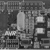
Page 5
... Overview AT90USBKey Hardware User Guide Using the AT90USBKey This chapter describes the AVRUSBKey and all its resources. Figure 2-1 . AT90USBKey Overview Section 2 2-5 7627A–AVR–04/06 ...
Page 6
... Power Supply Sources USB powered When used as a USB device bus powered application, the AVRUSBKey can be directly Battery powered The external battery connector should be used when the AT90USBKey is used as a 2-6 7627A–AVR–04/06 The on-board power supply circuitry allows two power supply configurations: ...
Page 7
... VBUS pin of its USB mini AB connector. A couple of transistors allows the UVCON pin of the AT90USB to control the VBUS generation (See Figure 2-3). In this mode the AT90USBKey is powered by external battery power supply source. Figure 2-3 . VBUS generator schematic ...
Page 8
... To use the USB interface of the AT90USB, the clock source should always be a crystal or external clock oscillator (the internal 8MHz RC oscillator can not be used to operate with the USB interface). Only the following crystal frequency allows proper USB operations: 2MHz, 4MHz, 6MHz, 8MHz, 12MHz, 16MHz. The AT90USBKey comes with a default 8MHz crystal oscillator. VCC ...
Page 9
... On-board Resources 2.4.1 USB 2.4.2 Joystick AT90USBKey Hardware User Guide The AVRUSBKey is supplied with a standard USB mini A-B receptacle. The mini AB receptacle allows to connect both a mini A plug or a mini B plug connectors. Figure 2-5 . USB mini A-B Receptacle J3 1-V_BUS 2-D- 3-D+ ...
Page 10
... Temperature Sensor 2-10 7627A–AVR–04/06 The AT90USBKey includes 2 bi-color LEDs (green/red) implemented on one line. They are connected to the high nibble of “Port D” of AT90USB (PORTD[4..7]). To light on a LED, the corresponding port pin must drive a high level. To light off a LED, the corresponding port pin must drive a low level. ...
Page 11
... AT90USBKey Hardware User Guide The NTC thermistor used in AT90USBKey has a resistance of 100 KΩ and a beta-value of 4250 ±3%. By the use of the following equation, the temperature (T) can be calculated: β β ⎛ ⎞ ⎠ Where Thermistor value (Ω temperature (°Kelvin) T ß = 4250 ±3% ± ...
Page 12
... Figure 2-8 . Thermistor Schematic PF[7..0] For mass-storage class demonstration purpose, the AT90USBKey provides two on-chip serial Flash memories (AT45DB642D) connected to the AT90USB Serial Port Interface (SPI). The data-flash chip select signals are connected to PortE bit 0 and bit 1 of the AT90USB (See Figure 2-9) ...
Page 13
... The HWB pin is active only if the HWBE fuse is set (default factory configuration). The AT90USB can be programmed using specific JTAG link. To use the AVR JTAGICEmkII with an AT90USBKey an optional HE10 connector should be soldered to J9 footprint. Then the JTAG probe can be connected to the AT90USBKey as shown in . Figure 2-10 ...
Page 14
... Note: See AVR Studio® on-line Help for information. The AT90USBKey can be used for debugging with JTAG ICE MK II. Connect the JTAG ICE mkII as shown in Figure 2-10, for debugging, please refer to AVR Studio® Help information. ...
Page 15
... AT90USBKey Hardware User Guide Figure 3-1 . Troubleshooting Guide Problem The Green “VCC-ON” LED is not on No power supply AVRUSBKey does not work The AVR JTAG ICE probe is not connected The memory lock bits are programmed The AT90USB cannot be The fuse bits are ...
Page 16
... AT90USBKey Hardware User Guide Technical Specifications System Unit – Physical Dimensions .....................................................L=90 x W=30 x H=8 mm – Weight ...........................................................................................................12 g Operating Conditions – Internal Voltage Supply ............................................................................... 3.3V – External Voltage Supply .........................................................................8V -15V Connections – USB Connector ......................................................................Mini AB receptacle – USB Communications .......................................................Full speed/low speed – ...
Page 17
... AT90USBKey Hardware User Guide For Technical support, please contact avr@atmel.com. When requesting technical support, please include the following information: Which target AVR device is used (complete part number) Target voltage and speed Clock source and fuse setting of the AVR Programming method (ISP, JTAG or specific Boot-Loader) Hardware revisions of the AVR tools, found on the PCB Version number of AVR Studio ...
Page 18
... AT90USBKey Hardware User Guide On the next pages, the following documents of AT90USBKey are shown: Complete schematics, Bill of materials. Section 6 Complete Schematics 6-18 7627A–AVR–04/06 ...
Page 19
... PE7 PE5 PE3 PE1 PE0 PE2 PE4 PE6 PF7 PF5 PF3 PF1 PF0 PF2 PF4 PF6 AT90USBKey Hardware User Guide Figure 6-1 . Schematics PD7 PD5 PD3 PC3 PD1 PC1 PD0 PC0 PD2 PC2 PD4 PD6 PA2 PD7 49 PA2 PA1 PD6 50 PA1 ...
Page 20
... Complete Schematics 6-20 7627A–AVR–04/06 Figure 6-2 . Schematics PF3 PF0 AT90USBKey Hardware User Guide ...
Page 21
... SW3 U2, AT90USBKey Hardware User Guide Table 6-1 . Bill of material Part ESD protection (PGB0010603) 100nF 1uF 220nF 15pF 4.7uF 33nF LED BI-COLOUR/ LSGT670 TOPLED/ LPM676-K2M1 DII LL4148-7 USB mini AB receptacle Surface mount CON 2x5 (2.54mm) 1.27 mm Dual header Connector MTA 2 cts right angle ...
Page 22
... Disclaimer: The information in this document is provided in connection with Atmel products. No license, express or implied, by estoppel or otherwise,to anyintellectu- alproperty right is granted by this document or in connection with the sale of Atmel products. EXCEPT AS SET FORTH IN ATMEL’S TERMS AND CONDI-TIONS OF SALE LOCATED ON ATMEL’S WEB SITE, ATMEL ASSUMES NO LIABILITY WHATSOEVER AND DISCLAIMS ANY EXPRESS, IMPLIED OR STATUTORYWAR- RANTY RELATING TO ITS PRODUCTS INCLUDING, BUT NOT LIMITED TO, THE IMPLIED WARRANTY OF MERCHANTABILITY, FITNESS FOR A PARTICU- LARPURPOSE, OR NON-INFRINGEMENT ...