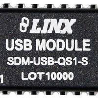
SDM-USB-QS-S Linx Technologies Inc, SDM-USB-QS-S Datasheet - Page 2

SDM-USB-QS-S
Manufacturer Part Number
SDM-USB-QS-S
Description
RF Modules & Development Tools USB Module
Manufacturer
Linx Technologies Inc
Datasheet
1.SDM-USB-QS-S_.pdf
(7 pages)
Specifications of SDM-USB-QS-S
Board Size
20.6 mm x 16 mm x 3.2 mm
Minimum Operating Temperature
0 C
Supply Voltage (min)
4.5 V
Product
RF Modules
Supply Voltage (max)
5.5 V
Maximum Operating Temperature
+ 70 C
Lead Free Status / RoHS Status
Lead free / RoHS Compliant
Available stocks
Company
Part Number
Manufacturer
Quantity
Price
Company:
Part Number:
SDM-USB-QS-S
Manufacturer:
ADI
Quantity:
745
ABSOLUTE MAXIMUM RATINGS
PIN ASSIGNMENTS
Figure 2: SDM-USB-QS-S Pinout (Top View)
Page 2
ELECTRICAL SPECIFICATIONS
Parameter
POWER SUPPLY
Operating Voltage
Supply Current
UART SECTION
Data Rate
Data Output:
EEPROM Size
USB SECTION
Data Output:
Single-Ended RX Threshold
Differential Common Mode
Differential Input Sensitivity
Driver Output Impedance
ENVIRONMENTAL
Operating Temperature Range
Logic Low
Logic High
Logic Low
Logic High
Supply Voltage V
Any Input or Output Pin
Max Current Sourced By Outputs
Operating Temperature
Storage Temperature
Soldering Temperature
*NOTE*
damage to the device. Furthermore, extended operation at these maximum
ratings may reduce the life of this device.
*CAUTION*
This product incorporates numerous static-sensitive components.
Always wear an ESD wrist strap and observe proper ESD handling
procedures when working with this device. Failure to observe this
precaution may result in module damage or failure.
Exceeding any of the limits of this section may lead to permanent
CC
Designation
1
2
3
4
5
6
7
8
UD
UV
UC
UV
UV
UV
V
V
V
USBDP
USBDM
GND
VCC
SUSP_IND
RX_IND
TX_IND
485_TX
I
CC
CC
–
OH
–
OL
RVZ
OH
OM
DIF
OL
SE
0.0003
Min.
4.35
DATA_OUT
0.3
3.2
0.0
2.8
0.8
0.8
0.2
0.0
29
–
–
DATA_IN
-0.5
-0.5
-65
0
DCD
DSR
RTS
CTS
DTR
+225°C for 10 seconds
RI
Typical
26.0
5.0
0.4
4.1
–
–
–
–
–
–
–
–
–
16
15
14
13
12
10
11
9
24
to
to V
to
to
1,024
Max.
5.25
28.0
CC
+70
3.0
0.6
4.9
0.3
3.6
2.0
2.5
44
–
+150
+6.0
+70
+ 0.5
Units
Mbps
VDC
VDC
VDC
VDC
VDC
VDC
VDC
VDC
Bits
mA
°
Ω
VDC
VDC
C
mA
°C
°C
Notes
–
–
–
–
–
–
–
–
–
–
–
–
–
PIN DESCRIPTIONS
Pin #
10
11
12
13
14
15
16
1
2
3
4
5
6
7
8
9
DATA_OUT
SUSP_IND
DATA_IN
USBDM
RX_IND
TX_IND
USBDP
485_TX
Name
GND
DCD
DTR
CTS
RTS
DSR
V
RI
CC
Goes low during USB Suspend Mode. This pin can be used to
This line will pulse low when receiving data from the USB bus.
power down external logic when the host puts the USB bus
This line will pulse low when transmitting data on the USB
bus. This allows for the connection of a LED indicator.
This allows for the connection of a LED indicator.
Data Terminal Ready control / handshake output
Request To Send control / handshake output
Transmit enable line for RS-485 applications
Data Set Ready control / handshake input
Clear To Send control / handshake input
Transmit asynchronous data output
Receive asynchronous data input
Data Carrier Detect control / input
Ring Indicator control input
USB data signal minus
Positive power supply
USB data signal plus
into suspend mode.
Ground supply
Description
Page 3


