XDM2510HP RFM, XDM2510HP Datasheet - Page 11
XDM2510HP
Manufacturer Part Number
XDM2510HP
Description
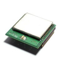
RF Modules & Development Tools 2.4 GHz WirelessHART Pin Version
Manufacturer
RFM
Datasheet
1.XDM2510HP.pdf
(16 pages)
Specifications of XDM2510HP
Board Size
1.05 in x 0.985 in
Minimum Frequency
2.4 GHz
Minimum Operating Temperature
- 40 C
Supply Voltage (min)
3.3 V
Product
RF Modules
Maximum Frequency
2.4835 GHz
Output Power
8 dBm
Antenna
U.FL Connector
Supply Voltage (max)
5.5 V
Supply Current
18 mA
Maximum Operating Temperature
+ 85 C
Lead Free Status / RoHS Status
Lead free / RoHS Compliant


8.3 /LED
The XDM2510H provides an output to drive a status LED. This signal indicates network connectivity information,
which is useful during XDM2510H system installation. Alternatively, the XDM2510H status may be polled using
the serial Get Parameter request with the module state parameter.
8.4 Settable I/O Modes
The XDM2510H offers a choice of two I/O modes. The functionality of the interface will be determined by the set-
ting MODE input.
Both modes provide a means of transmitting and receiving serial data through the wireless network, and a com-
mand interface that provides synchronized time stamping, local configuration and diagnostics. Mode 1 imple-
ments an 8-bit, no parity, 9600 baud, three, four or five-signal serial interface with bidirectional packet-level flow
control operating at 9600 b/s. In certain designs, one or two of the serial handshake signals may be optional for
reduced pin count. Please refer to detailed descriptions of signals. Mode 3 implements an 8-bit, no parity, 9,600
baud, five-signal serial interface with bidirectional packet-level flow control and byte-level flow control in the
XDM2510H-to-microcontroller direction only.
8.4.1 Mode 1 - Three/Four/Five Signal Serial Interface (9600 b/s)
XDM2510H Mode 1 provides a three, four, or five-signal serial interface optimized for low-powered embedded
applications, and in certain designs may provide a lower pin count serial solution. The Mode 1 serial interface is
comprised of the data pins UART_TX and UART_RX, with handshake pins /MT_RTS, /MT_CTS, /SP_CTS used
for bidirectional flow control. The /MT_RTS signal is ideal for designs where the host microcontroller requires ex-
tra time to prepare to receive a packet. For example, when the host microcontroller sleeps periodically and re-
quires a wake-up signal prior to receiving a packet. Refer to Table15 for information on each pin, including details
on which pins are optional.
www.RFM.com
©2010-2011 by RF Monolithics, Inc.
t
t
High
Single blink (750 ms low, 3 s high)
Double blink (750 ms low, 750 ms high, 750 ms low, 3 s high)
Triple blink (750 ms low, 750 ms high, 750 ms low, 750 ms high, 750 ms
low, 3 s high)
Low
strobe
response
/TIME Parameters
E-mail:
Setting
MODE Pin Setting
info@rfm.com
/LED Signal Behavior
TIME strobe pulse width
TIME strobe active low assertion to start of time packet
Technical support +1.800.704.6079
E-mail: tech_sup@rfm.com
Meaning
Externally tied low
Mode 1
Table 12
Table 13
Table 14
Off, or in sleep mode
On, and searching for potential network
On, and attempting to join the network
On, and attempting to establish redundant links
On, fully configured into network with redundant parents
Externally tied high
XDM2510H State
Mode 3
Minimum
125
Maximum
100
XDM2510H - 03/17/11
Page 11 of 16
Units
ms
µs
Related parts for XDM2510HP
Image
Part Number
Description
Manufacturer
Datasheet
Request
R

Part Number:
Description:
ASH RX 115.2 KBPS 433.92 MHZ
Manufacturer:
RFM
Datasheet:

Part Number:
Description:
RFIC TRANCEIVER MULTI-CHANNEL FS
Manufacturer:
RFM
Datasheet:

Part Number:
Description:
ASH TX 115.2 KBPS 433.92 MHZ
Manufacturer:
RFM
Datasheet:
Part Number:
Description:
Filters 1602MHz BW=61MHz
Manufacturer:
RFM
Datasheet:

Part Number:
Description:
RESONATOR, SM3030-6
Manufacturer:
RFM
Datasheet:

Part Number:
Description:
RESONATOR, SM3030-6
Manufacturer:
RFM
Datasheet:

Part Number:
Description:
RESONATOR, SM3030-6
Manufacturer:
RFM
Datasheet:

Part Number:
Description:
RESONATOR, SM5035-4
Manufacturer:
RFM
Datasheet:
Part Number:
Description:
RESONATOR 418MHZ SM5035-4
Manufacturer:
RFM
Datasheet:
Part Number:
Description:
RESONATOR 315 MHZ SMD
Manufacturer:
RFM
Datasheet:

Part Number:
Description:
10-Terminal Ceramic Surface-Mount Case 7 x 5 mm Nominal Footprint
Manufacturer:
RFM [RF Monolithics, Inc]
Datasheet:
Part Number:
Description:
QUAD-BAND GSM850/GSM/DCS/PCS POWER AMP MODULE
Manufacturer:
RFM [RF Monolithics, Inc]
Datasheet:
Part Number:
Description:
402 to 405 MHz Medical Band Front-end Filter
Manufacturer:
RFM [RF Monolithics, Inc]
Datasheet:
Part Number:
Description:
674.03 MHz SAW Resonator
Manufacturer:
RFM [RF Monolithics, Inc]
Datasheet: