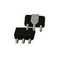
AH31-PCB240 TriQuint, AH31-PCB240 Datasheet - Page 3

AH31-PCB240
Manufacturer Part Number
AH31-PCB240
Description
RF Modules & Development Tools 220-260MHz Eval Brd 19dB Gain
Manufacturer
TriQuint
Datasheet
1.AH31-PCB75.pdf
(7 pages)
Specifications of AH31-PCB240
Board Size
4.25 mm x 4.6 mm x 1.6 mm
Minimum Frequency
50 MHz
Minimum Operating Temperature
- 40 C
Supply Voltage (min)
5 V
Product
RF Modules
Maximum Frequency
1 GHz
Supply Voltage (max)
6 V
Supply Current
150 mA
Maximum Operating Temperature
+ 85 C
For Use With/related Products
AH31
Lead Free Status / RoHS Status
Lead free / RoHS Compliant
Other names
1067223
WJ Communications, Inc • Phone 1-800-WJ1-4401 • FAX: 408-577-6621 • e-mail: sales@wj.com • Web site: www.wj.com, www.TriQuint.com
20
19
18
17
16
15
Frequency
Gain
S11
S22
Output P1dB
Output IP3
Noise Figure
Bias
Frequency
Gain
S11
S22
Output P1dB
Output IP3
Noise Figure
Bias
20
19
18
17
16
15
55
150
Notes:
1. The amplifier should be connected directly to a +5 V regulator; no dropping resistor is required.
2. If no DC signal is present at the input (pin 1), C1 can be removed. The gate is internally grounded in the amplifier.
3. R2 is used as a placeholder for a different application circuit. It can be removed from the circuit.
4. C2 (from the silkscreen) is not utilized in this application circuit.
S11
S22
Typical Performance
Typical Performance
AH31
High Dynamic Range IF Amplifier
65
160
S11
Frequency (MHz)
Frequency (MHz)
S-Parameters
S-Parameters
75
75 MHz
19.5 dB
-21 dB
-17 dB
+22 dBm
+42 dBm
2.6 dB
+5 V @ 150 mA
170 MHz
19.2 dB
-13 dB
-14 dB
+21 dBm
+42 dBm
2.3 dB
+5 V @ 150 mA
Application Circuit: 155 – 185 MHz (AH31-PCB170)
170
Application Circuit: 65 – 85 MHz (AH31-PCB75)
S22
85
180
S21
S21
95
190
0
-5
-10
-15
-20
-25
0
-5
-10
-15
-20
-25
3.5
2.5
1.5
2.5
2.0
1.5
1.0
0.5
0.0
3
2
1
55
150
RF IN
65
160
RF IN
Frequency (MHz)
1000 pF
Frequency (MHz)
Noise Figure
.018 μ F
Noise Figure
C1
C1
170
75
82 nH
220 nH
L1
L1
3.3 Ω
5.1 Ω
R1
R1
180
85
C3
4.7 pF
C3
12 pF
AH31
AH31
190
95
Specifications and information are subject to change without notice
330 nH
330 nH
46
44
42
40
38
36
46
44
42
40
38
36
V
L2
V
55
150
L2
S
S
= +5 V
= +5 V
0 Ω
R2
0 Ω
R2
C5
.018 μ F
C5
.018 μ F
160
65
1000 pF
.018 μ F
Frequency (MHz)
Frequency (MHz)
C4
C4
Output IP3
Output IP3
170
75
RF
RF
Page 3 of 7 January 2008
180
85
190
95


