WSN802GCA RFM, WSN802GCA Datasheet - Page 4
WSN802GCA
Manufacturer Part Number
WSN802GCA
Description
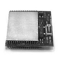
WiFi / 802.11 Modules & Development Tools 802.11b/g Sensor Mod Cast. Ver w/Chip Ant
Manufacturer
RFM
Datasheet
1.WSN802GCA.pdf
(6 pages)
Specifications of WSN802GCA
Wireless Frequency
2.4 GHz
Interface Type
UART, SPI
Modulation
BPSK, QPSK, CCK
Security
802.1x, WPA2
Operating Voltage
3.63 V
Output Power
10 mW
Antenna
Chip
Operating Temperature Range
- 40 C to + 85 C
For Use With/related Products
WSN802G
Lead Free Status / RoHS Status
Lead free / RoHS Compliant


WSN802G I/O Pad Descriptions
www.RFM.com E-mail: info@rfm.com
©2009-2010 by RF Monolithics, Inc.
Pin
10
11
12
13
14
15
16
17
18
19
20
21
22
23
24
25
26
27
28
29
30
1
2
3
4
5
6
7
8
9
RADIO_TXD
RADIO_RXD
/HOST_CTS
/HOST_RTS
WAKE_OUT
3.3V_OUT
ADC_REF
WAKE_IN
DIAG_RX
DIAG_TX
/RESET
GPIO0
PWM0
GPIO2
GPIO1
GPIO3
Name
RSVD
RSVD
ADC0
ADC1
MISO
MOSI
SCLK
GND
VCC
GND
GND
GND
GND
/SS
I/O
I/O
I/O
I/O
I/O
I/O
I/O
I/O
I/O
O
O
O
O
O
O
O
-
-
-
-
-
-
-
I
I
I
I
I
I
I
I
Power supply and signal ground. Connect to the host circuit board ground.
Diagnostic serial port output.
Diagnostic serial port input.
Configurable digital I/O port 0. An internal weak pull up is provided when configured as an input.
Serial data output from the radio.
Serial data input to the radio.
UART/SPI flow control output. The module sets this line low to indicate it is ready to accept data from the host
on the RADIO_RXD or MOSI input. When the module sets this line high, the host must stop sending data.
UART flow control input. The host sets this line low to allow data to flow from the module on the RADIO_TXD
pin. When the host sets this line high, the module will stop sending data to the host.
16-bit pulse-width modulated output 0 with internal low-pass filter. Filter is first-order, with a 159 Hz 3 dB
bandwidth, 10K output resistance.
Configurable digital I/O port 2. An internal weak pull up is provided when configured as an input.
Configurable digital I/O port 1. An internal weak pull up is provided when configured as an input.
Configurable digital I/O port 3. An internal weak pull up is provided when configured as an input.
Reserved pin. Leave unconnected.
Power supply input, +3.0 to +3.63 Vdc.
Power supply and signal ground. Connect to the host circuit board ground.
Power supply and signal ground. Connect to the host circuit board ground.
Active low module hardware reset.
10-bit ADC input 0. ADC full scale reading can be referenced to the module’s +1.8 V regulated supply.
10-bit ADC input 1. ADC full scale reading can be referenced to the module’s +1.8 V regulated supply.
SPI master in, slave out function. This pin is an input when the module is operating as a master, and is an
output when the module is operating as a slave.
SPI master out, slave in function. This pin is an output when the module is operating as a master, and is an
input when the module is operating as a slave.
SPI active low slave select. This pin is an output when the module is operating as a master, and an input
when it is operating as a slave.
SPI clock signal. This pin is an output when operating as a master, and an input when operating as a slave.
Module’s +3.3 V regulated supply, available to power external sensor circuits. Current drain on this output
should be no greater than 50 mA.
Module’s +1.8 V regulated supply, used for ratiometric ADC readings. Current drain on this output should be
no greater than 10 mA.
Active high interrupt input to wake the module from timer sleep. Can be used to wake module on event, etc.
Active high output asserted when module wakes from timer sleep. Can be used to wake an external device.
Connect to the host circuit board ground plane.
Reserved pin. Leave unconnected.
Connect to the host circuit board ground plane.
Description
WSN802GCA/PA - 10/05/10
Page 4 of 6
Related parts for WSN802GCA
Image
Part Number
Description
Manufacturer
Datasheet
Request
R

Part Number:
Description:
ASH RX 115.2 KBPS 433.92 MHZ
Manufacturer:
RFM
Datasheet:

Part Number:
Description:
RFIC TRANCEIVER MULTI-CHANNEL FS
Manufacturer:
RFM
Datasheet:

Part Number:
Description:
ASH TX 115.2 KBPS 433.92 MHZ
Manufacturer:
RFM
Datasheet:
Part Number:
Description:
Filters 1602MHz BW=61MHz
Manufacturer:
RFM
Datasheet:

Part Number:
Description:
RESONATOR, SM3030-6
Manufacturer:
RFM
Datasheet:

Part Number:
Description:
RESONATOR, SM3030-6
Manufacturer:
RFM
Datasheet:

Part Number:
Description:
RESONATOR, SM3030-6
Manufacturer:
RFM
Datasheet:

Part Number:
Description:
RESONATOR, SM5035-4
Manufacturer:
RFM
Datasheet:
Part Number:
Description:
RESONATOR 418MHZ SM5035-4
Manufacturer:
RFM
Datasheet:
Part Number:
Description:
RESONATOR 315 MHZ SMD
Manufacturer:
RFM
Datasheet:

Part Number:
Description:
Power Management Development Tools Wireless Temperature and Humidity Sensor
Manufacturer:
Powercast
Datasheet:

Part Number:
Description:
Power Management Development Tools Wireless Sensor Kit w/ WSG-101-SERIAL
Manufacturer:
Powercast
Datasheet:
Part Number:
Description:
Power Management Development Tools Wireless Sensor Kit w/ WSG-101-BACNET-IP
Manufacturer:
Powercast
Part Number:
Description:
10-Terminal Ceramic Surface-Mount Case 7 x 5 mm Nominal Footprint
Manufacturer:
RFM [RF Monolithics, Inc]
Datasheet: