LPR2430 RFM, LPR2430 Datasheet

Zigbee / 802.15.4 Modules & Development Tools 1mW Transmit Power 250 kb/s

LPR2430

Manufacturer Part Number
LPR2430
Description
Zigbee / 802.15.4 Modules & Development Tools 1mW Transmit Power 250 kb/s
Manufacturer
RFM
Datasheet

Specifications of LPR2430

Wireless Frequency
2.4 GHz
Modulation
OQPSK
Operating Voltage
3.3 V
Output Power
1 mW
Operating Temperature Range
- 40 C to + 85 C
For Use With/related Products
CC2430
Lead Free Status / RoHS Status
Lead free / RoHS Compliant

Available stocks

Company
Part Number
Manufacturer
Quantity
Price
Part Number:
LPR2430
Manufacturer:
RFM
Quantity:
12 800
Part Number:
LPR2430A
Manufacturer:
RFM
Quantity:
12 800
Part Number:
LPR2430ADK
Manufacturer:
RFM
Quantity:
12 800
Part Number:
LPR2430DK
Manufacturer:
RFM
Quantity:
12 800
Part Number:
LPR2430ER
Manufacturer:
RFM
Quantity:
12 800
Part Number:
LPR2430ER
Manufacturer:
MURATA/村田
Quantity:
20 000
The LPR2430 2.4 GHz transceiver module is a low cost, low-power solution for
peer-to-peer, point-to-point and point-to-multipoint wireless designs. LPR2430 mod-
ules provide the flexibility and versatility to serve applications ranging from cable re-
placements to sensor networks. Based on the IEEE 802.15.4 wireless standard, the
LPR2430 module is easy to integrate and provides robust wireless communications
in applications where full mesh network operation is not required. The LPR2430 in-
cludes CNL V2.0 Network Layer firmware which features a flexible and simple-to-use
Application Programming Interface.
LPR2430 Absolute Maximum Ratings
LPR2430 Electrical Characteristics
www.RFM.com E-mail: info@rfm.com
©2009 by RF Monolithics, Inc.
All Input/Output Pins
Non-Operating Ambient Temperature Range
Operating Frequency Range
Operating Frequency Tolerance
Spread Spectrum Method
Modulation Type
Number of RF Channels
RF Data Transmission Rate
Symbol Rate Tolerance
RF Channel Spacing
Receiver Sensitivity, 10E-5 BER
Upper Adjacent Channel Rejection, +5 MHz
Lower Adjacent Channel Rejection, -5 MHz
Upper Alternate Channel Rejection, +10 MHz
Lower Alternate Channel Rejection, -10 MHz
Maximum RF Transmit Power
Transmit Power Adjustment
Optimum Antenna Impedance
2.4 GHz Spread Spectrum Transceiver Module
Small Size, Light Weight, Low Cost
Sleep Current less than 3 µA
FCC, Canadian IC and ETSI Certified for Unlicensed Operation
Characteristic
Rating
Sym
-0.3 to +3.6
-40 to +85
Value
Notes
Units
o
Minimum
V
C
2405
-300
Direct Sequence
O-QPSK
Transceiver
Typical
LPR2430
250
Shown with Shield Removed
-92
15
41
30
55
53
50
5
0
DEVELOPMENT KIT
802.15.4
Module
(Info
Click
Maximum
LPR2430 - 06/19/09
2475
300
120
26
here)
Page 1 of 6
Units
MHz
MHz
dBm
dBm
ppm
kb/s
kHz
dB
dB
dB
dB
dB
W

Related parts for LPR2430

LPR2430 Summary of contents

Page 1

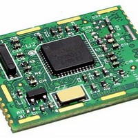
... FCC, Canadian IC and ETSI Certified for Unlicensed Operation The LPR2430 2.4 GHz transceiver module is a low cost, low-power solution for peer-to-peer, point-to-point and point-to-multipoint wireless designs. LPR2430 mod- ules provide the flexibility and versatility to serve applications ranging from cable re- placements to sensor networks ...

Page 2

... CAUTION: Electrostatic Sensitive Device. Observe precautions when handling. www.RFM.com E-mail: info@rfm.com ©2009 by RF Monolithics, Inc. Sym Notes Minimum Typical 1.2, 2.4, 4.8, 9.6 (default), 19.2, 28.8, 38.4, 57.6, 76.8, 115.2 -0 -40 Maximum Units 3.3 V bits MW 16 bits kb/s 0 +5.5 Vdc µ Page LPR2430 - 06/19/09 ...

Page 3

... PWM outputs and module configuration services. In addition, CNL supports analog and digital I/O binding, which maps an ADC measurement and the states of two digital inputs on one LPR2430 to a PWM output and two digital outputs on another LPR2430. See the LPR2430 Series Integration Guide for complete details of the CNL API ...

Page 4

... GPIO4 7 I/O as UART flow control output. The LPR2430 sets this line low to indicate it is ready to accept data from the host on the (/HOST_CTS ) RADIO_RXD input. When the LPR2430 sets this line high, the host must stop sending data. The default state is GPIO4. ...

Page 5

... E-mail: info@rfm.com ©2009 by RF Monolithics, Inc. Figure 2 Trace Separation from 50 Ohm Microstrip 100 mil 150 mil 200 mil 250 mil 300 mil Figure 4 Length of Trace Run Parallel to Microstrip 125 mil 200 mil 290 mil 450 mil 650 mil Page LPR2430 - 06/19/09 ...

Page 6

... Reflow Profile An example solder reflow profile for mounting the radio module on its host circuit board is shown in Figure 5. Note: Specifications subject to change without notice. www.RFM.com E-mail: info@rfm.com ©2009 by RF Monolithics, Inc. Figure 5 Part # M-2430-0000, Rev A Page LPR2430 - 06/19/09 ...

Related keywords