OCB100-KIT Optek, OCB100-KIT Datasheet
OCB100-KIT
Specifications of OCB100-KIT
Available stocks


Related parts for OCB100-KIT


OCB100-KIT Summary of contents
Page 1
... The OCB100 Series Auto-Calibrating Boards take the guesswork out of tuning the sensor for your unique applications. Auto-Calibration Design Kit OCB100-KIT ...
Page 2
... Content Kit Description Included in your OCB100-KIT OCB100CZ Theory of operation Powering up the OCB100CZ Package Drawing Calibration Circuit Drawing OPB732WZ Theory of operation Using the OPB732CZ with the OCB100CZ 2 Package Drawing OPB885Z Theory of operation Using the OPB885Z with the OCB100CZ Package Drawing OPB350 Series & OCB350 Series ...
Page 3
... KIT DESCRIPTION The OCB100-KIT design kit provides engineers an opportunity to become familiar with the capabilities of a variety of basic optoelec- tronic sensor types: transmissive, reflective, and fluid. The kit includes an automatic calibration circuit card that interfaces with each sensor to make evaluation of the sensor much easier. In addition, the calibra- tion PCB can be interfaced to almost any optoelectronic sensor via the onboard Molex 70553-0038 four pin header ...
Page 4
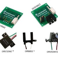
... INCLUDED IN YOUR OCB100-KIT DESIGN KIT • OCB100CZ — PCBoard Calibration Circuit (includes OCB100 - MC24 mating cable) • OPB350C125Z — Fluid Sensor for 0.125” [3.18mm] O.D. tubing • OPB732CZ — Medium distance reflective object sensor. • OPB885CZ — Slotted Switch 0.375” [9.53mm] slot width. ...
Page 5
... THEORY OF OPERATION OCB100 The OCB100 series is designed to minimize the change of optical de- vices due to manufacturing variance, temperature change, and device aging. This system can be used to calibrate either reflective or inter- ruptive devices to provide a consistent output, thus eliminating the need to confirm either the LED drive resistance or the phototransistor load resistance ...
Page 6
... Vcc while “Logic Out B” (mating connector blue wire) switches when the optical output signal increases above approxi- mately 2/3 of Vcc. As with all optical devices with logic outputs, the switching condition is consistent with the phototransistor receiving a preset light level. OCB100-KIT ...
Page 7
... Reflective devices / reflective switches / reflective encoders • Specialty devices / fluid sensors POWERING UP THE OCB100CZ The OCB100CZ should be powered by a 5.0V ± 0.5V, 50mA mini- mum regulated power supply. You can also use three 1.5V AA batteries connected in series in a battery holder such as P/N SBH331AS available from batteryholders. ...
Page 8
... OCB100-KIT ...
Page 9
... OPTEK gives you the tools to help you take your ideas to market. 9 ...
Page 10
... When the light strikes an object reflected back toward 10 the phototransistor. The amount of current Ic phototransistor is dependent upon the amount of light striking it. The following graph shows the effect of target distance on the output current of the OPB732. collector current of 0.25mA @ VCE = 0.4V and OCB100-KIT generated from the (ON) ...
Page 11
... OCB100CZ”. Plug the OPB732CZ connector into the 4 pin Molex mating connec- tor on the OCB100CZ , and then apply power to the circuit. Adjust the phototransistor emitter load resistor to equal approximately 10Kohms (RL @10K) by placing the shorting bar on the board betweens pins 2 & ...
Page 12
... In practice, the OPB732 family LEDs can 12 be driven at DC current levels up to 50mA (maximum rating at room temperature). See the device data sheet at www.optekinc.com for more details. Applicable part numbers: OPB732, OPB732CZ, OPB732WZ cannot reach ½ Vcc even when OUT OCB100-KIT has risen to OUT ...
Page 13
... Color-Pin # Function Red - 1 Anode Black - 2 Cathode OPTEK gives you the tools to help you take your ideas to market. 15.49 ±0.25 Anode - 1 .610 ±.01 2.16 ±0.25 .085 ±.01 4.32 ±0.25 .170 ±.01 Cathode - 2 2X 2.44 ± ...
Page 14
... Analysis of these graphs shows a narrower signal area next to both 14 towers. This effect is due to the beam angle and acceptance angle of the LED and phototransistor of about 40° and the presence of a .05”[1.27mm] wide aperture in front of each component. collector current of the (ON) OCB100-KIT ...
Page 15
... Top to Bottom 1.0 0.8 Left to Right 0.6 0.4 0.2 0.0 0.00 0.05 OPTEK gives you the tools to help you take your ideas to market. OPB885 - Flag Next to Emitter Right to Left 0.10 0.15 0.20 Distance (inches) OPB885 - Flag Next to Sensor Right to Left 0.10 ...
Page 16
... LED drive maximum 14mA, it may become apparent to you that this specification does not guarantee every OPB885CZ can reach 1.0mA @ IF=14mA, and therefore it may be necessary to change (ON ½ Vcc. If Vcc = 5V and OUT will be approximately 2.5 volts. Therefore OUT www.optekinc.com shows that the guarantee of 1.3mA minimum @ (ON) OCB100-KIT ...
Page 17
... A sample label / liner is included in this OCB100-KIT. Try the following experiment: Insure that the shorting bar is placed between pins 2 & set the load resistor at approximately 10K ohms. Place the gap between the two labels in the center of the optical path ...
Page 18
... AWG 3 5.08 ±0.25 .200 ±.01 4 16.38 ±0.25 .645 ±.01 Emitter - 4 Color-Pin # Function Red - 1 Black - 2 White - 3 Green - 4 Collector - 3 OCB100-KIT C L 2.03 ±0.25 .080 ±.01 DIMENSIONS ARE IN INCHES AND [MILLIMETERS]. Anode Cathode Collector Emitter ...
Page 19
... PCBs. The OPB350W Series with 26 AWG wires are remote mount- able. The OCB350 Series incorporate the OPB350L Series directly onto the OCB100AZ (ref page 2) calibration circuit board. This series is configured to minimize the design effort needed to use a fluid sen- sor by utilizing the onboard calibration circuitry. Four visible LED lights are provided on the board to indicate whether the sensor has been calibrated and what its output state is ...
Page 20
... PCB mount for 1/4” tubing OPB350W250Z Wired assembly for 1/4” tubing, with mounting tabs OCB350L062Z OPB350L062Z mounted on OCB100AZ calibration circuit board OCB350L125Z OPB350L125Z mounted on OCB100AZ calibration circuit board OCB350L187Z OPB350L187Z mounted on OCB100AZ calibration circuit board OCB350L250Z OPB350L250Z mounted on OCB100AZ calibration circuit board OCB100-KIT ...
Page 21
... A short length of 1/8” clear tubing is included in the OCB100-KIT. Try the following experiment. Snap the tubing into place in the optical path of the OPB350C125Z. Calibrate the sensor. Insert water into the tubing sample ...
Page 22
... OPB350 Package Drawing 22 OCB100-KIT ...
Page 23
... For any additional information or questions please feel free to contact us via our applications hotline at 972.323.2488 OPTEK gives you the tools to help you take your ideas to market. 23 ...
Page 24
... OPTEK Technology 1645 Wallace Drive Carrollton, TX 75006 USA Telephone: 972.323.2200 Fax: 972.323.2396 sensors@optekinc.com www.optekinc.com OCB100-KIT OPTEK reserves the right to make changes at any time in order to improve design and to supply the best product possible. ...