OPB780KIT Optek, OPB780KIT Datasheet - Page 4
OPB780KIT
Manufacturer Part Number
OPB780KIT
Description
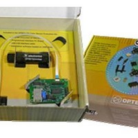
Optical Sensor Development Tools Color Sensing Kit
Manufacturer
Optek
Datasheet
1.OPB780KIT.pdf
(9 pages)
Specifications of OPB780KIT
Maximum Operating Temperature
+ 85 C
Minimum Operating Temperature
- 40 C
Description/function
Color sensor light to frequency kit
For Use With/related Products
OPB780
Lead Free Status / RoHS Status
Lead free / RoHS Compliant


OPB780-Kit
Color Sensor Evaluation Kit
is very important to understand its characteristics
relative to forward current and temperature.
below chart shows how the forward current of the LED
changes the Chromatic coordinates.
LED lowers the “Y” value while minimally changing the
“X” value.
(equivalent to sun light at 12 noon with no
contaminates in the air) has both “X” and “Y” chromatic
values of 1/3. Chromatic numbers below 1/3 consist of
more Blue or Green wavelengths and numbers above
1/3 consist of more Red or Yellow wavelengths. As
can be seen a forward current of approximately 4 mA
would provide the most optimum “Y” value.
One of the critical parts of the OPB780Z is the LED. It
As can be seen, increasing the forward current of the
Issue A.2
Page 4 of 9
0.35
0.34
0.33
0.32
0.31
0.30
0.29
11/09
Forward Current vs Chromaticity
T
OPTEK reserves the right to make changes at any time in order to improve design and to supply the best product possible.
A
The projected most optimum light
= 25° C
0.30
Coordinate
0.31
100 mA
50 mA
20 mA
X
1 mA
5 mA
0.32
Phone: (972) 323-2200 or (800) 341-4747
0.33
0.34
The
temperature.
value moves closer toward the optimum (1/3) value.
cooler the temperature, the closer the LED transmits to
the optimum chromatic values of “X”=1/3 and “Y”=1/3.
color resolution, the white LED should be driven with
at least 20 mA of forward current and operated at
room temperatures (approx. 25°C). These conditions
result in chromatic ranges of about “X”=0.31 and
“Y”=0.32.
on the angular position of the device to the object.
The graphs showing the typical variance of the Output
frequency of the device vs both Azmuth (twist) and
Zenith (bend) are shown in the two graphs.
The graphs show the change in chromaticity vs
In conclusion, the lower the forward current and the
In order to provide sufficient light levels and the best
The responsivity of the each diode group is dependent
0.35
0.34
0.33
0.32
0.31
0.30
OPTEK Technology Inc. — 1645 Wallace Drive, Carrollton, Texas 75006
Ambient Temperature vs Chromaticity
0.29
FAX: (972) 323-2396 sensors@optekinc.com www.optekinc.com
I
FP
= 20 mA
85° C
0.30
As the temperature reduces the “X”
50° C
Coordinate
0.31
25° C
X
0.32
0° C
-30° C
0.33
0.34
Related parts for OPB780KIT
Image
Part Number
Description
Manufacturer
Datasheet
Request
R

Part Number:
Description:
OPB606REFLECTIVE OBJECT SENSORS
Manufacturer:
OPTEK OPTEK Technologies
Datasheet:

Part Number:
Description:
Infrared Emitters High Intensity 890nm
Manufacturer:
Optek
Datasheet:
Part Number:
Description:
Infrared Emitters Infrared 890nm
Manufacturer:
Optek
Datasheet:

Part Number:
Description:
Infrared Emitters VCSEL
Manufacturer:
Optek
Datasheet:

Part Number:
Description:
Infrared Emitters SMD Gull
Manufacturer:
Optek
Datasheet:

Part Number:
Description:
Infrared Emitters SMD Axial
Manufacturer:
Optek
Datasheet:

Part Number:
Description:
Infrared Emitters SMD Flat Lens
Manufacturer:
Optek
Datasheet:
Part Number:
Description:
Infrared Emitters IR EMITTING DIODE
Manufacturer:
Optek
Datasheet:

Part Number:
Description:
Photointerruptors .2in SLOT INFRARED
Manufacturer:
Optek
Datasheet:

Part Number:
Description:
Photointerruptors .16in SLOT INFRARED
Manufacturer:
Optek
Datasheet:
Part Number:
Description:
OPB606REFLECTIVE OBJECT SENSORS
Manufacturer:
OPTEK OPTEK Technologies
Datasheet:

Part Number:
Description:
TRANSISTOR PNP GP HERMETIC SMD
Manufacturer:
TT Electronics/Optek Technology
Datasheet:
Part Number:
Description:
TRANSISTOR PNP GP HERMETIC SMD
Manufacturer:
TT Electronics/Optek Technology
Datasheet:
Part Number:
Description:
TRANSISTOR NPN GP HERMETIC SMD
Manufacturer:
TT Electronics/Optek Technology
Datasheet:

Part Number:
Description:
LED IR 880NM FLAT LENS 0805 SMD
Manufacturer:
TT Electronics/Optek Technology
Datasheet: