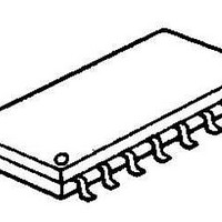
NJM13700M-TE2 NJR, NJM13700M-TE2 Datasheet - Page 2

NJM13700M-TE2
Manufacturer Part Number
NJM13700M-TE2
Description
Transconductance Dual
Manufacturer
NJR
Type
Amplifierr
Datasheet
1.NJM13600M.pdf
(6 pages)
Specifications of NJM13700M-TE2
Common Mode Rejection Ratio (min)
80 dB
Maximum Power Dissipation
700 mW
Mounting Style
SMD/SMT
Number Of Channels
2
Package / Case
DMP
Bandwidth
0.1 MHz
Input Offset Voltage
4 mV @ +/- 15V
Supply Voltage (max)
36 V
Supply Current
2.6 mA @ +/- 15 V
Maximum Operating Temperature
+ 85 C
Minimum Operating Temperature
- 40 C
Lead Free Status / RoHS Status
Lead free / RoHS Compliant
■ ABSOLUTE MAXIMUM RATINGS
Supply Voltage
Differential Input Voltage
Diode Bias Current
Amp Bias Current
Buffer Output Current
Power Dissipation
DC Input Voltage
Operating Temperature Range
Storage Temperature Range
( note ) At on a ceramic PCB ( 10x20x0.635 mm )
■ ELECTRICAL CHARACTERISTICS
Input Offset Voltage (V
Input Offset Voltage
V
Input Offset Change
Input Bias Current
Input Bias Current
Forward Transconductance
gm Tracking
Peak Output Current
Peak Output Current
Peak Output Current
Peak Output Voltage Positive
Peak Output Voltage Negative
Operating Current
V
V
Input Offset Current
CMRR
Common Mode Range
Cross Talk
Differential Input Current
Leakage Current
Input Resistance
Open Loop Bandwidth
Slew Rate
Buffer Input Current
Peak Buffer Output Voltage
( note1 ) Open unless otherwise specified. The inputs to the buffers are grounded and outputs are open.
( note2 ) R
O S
O S
O S
- 2 -
Including Diodes
Sensitivity Positive
Sensitivity Negative
I
PARAMETER
AB C
OUT
PARAMETER
=5kΩ connected from the buffer output to V
=500µA
O S
)
SYMBOL
CMR
SVR
I
V
V
V
L EAK
R
gm
I
CT
SR
I
I
I
SYMBOL
I
CC
O P
I C M
I O
I D
O P
I O
B
I N
V
I
T
T
V
V
P
ABC
+
I
I
D
O
opr
stg
/V
ID
IN
D
-
I
Diode Bias Current
5µA
(-20~+75˚C)
(-20~+75˚C)
R
R
R
R
R
R
I
∆V
∆V
20Hz<f<20kHz ( note2 )
I
I
( note2 )
( note2 )
ABC
ABC
ABC
ABC
L
L
L
L
L
L
=0,I
=0,I
=0,I
=0 (-20~+75˚C)
=∞,5µA
=∞,5µA
O S
O S
-
=5µA
=500µA,
=0,Input=±4V
=0
≤
and the input of buffer is connected to the transconductance amplifier output.
/∆V
/∆V
I
ABC
TEST CONDITION
ABC
ABC
ABC
(Refer to Test Circuit)
+
-
≤
( DMP16 ) 700 (note)
=5µA
=5µA
=500µA
≤
≤
500µA
I
I
ABC
ABC
two circuit
( DIP16 ) 570
RATINGS
-40~+125
36 or ±18
-40~+85
≤
≤
V
500µA
500µA
± 5
20
+
2
2
~V
,I
D
-
=500µA
6700
5400
MIN.
76.5
76.5
± 12
350
300
+12
( Ta=25˚C )
-12
80
10
10
-
-
-
-
-
-
-
-
-
-
-
-
-
-
-
-
UNIT
mW
mA
mA
mA
˚C
˚C
V
V
V
± 13.5
13600
+14.2
9600
-14.4
TYP.
-100
0.02
500
110
0.4
0.3
0.5
0.1
0.4
0.3
2.6
0.1
0.2
0.4
94
94
26
50
1
5
2
-
-
-
( V
13000
MAX.
650
100
100
0.6
+
5
5
5
5
8
5
-
-
-
-
-
-
-
-
-
-
-
-
-
-
-
-
-
/V
-
=±15V
6700
5400
MIN.
76.5
76.5
± 12
350
300
+12
-12
80
10
10
-
-
-
-
-
-
-
-
-
-
-
-
-
-
-
-
,
Ta=25˚C,I
13700
9600
-14.4
TYP.
+14.
13.5
-100
0.02
500
110
0.4
0.3
0.5
0.1
0.4
0.3
2.6
0.1
0.2
0.4
94
94
26
50
1
0
2
±
2
-
-
-
Ver.2006-04-06
13000
ABC
MAX.
650
100
100
0.6
4
4
5
3
5
8
5
-
-
-
-
-
-
-
-
-
-
-
-
-
-
-
-
=500µA )
UNIT
MHz
V/µs
mV
mV
mV
mV
mA
µA
µA
µS
µS
dB
µA
µA
µA
dB
dB
µA
dB
dB
nA
nA
kΩ
µA
V
V
V
V


