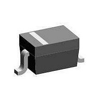
1N4448W-V-GS08 Vishay, 1N4448W-V-GS08 Datasheet - Page 3

1N4448W-V-GS08
Manufacturer Part Number
1N4448W-V-GS08
Description
Diodes (General Purpose, Power, Switching) Vr/75V Io/150mA
Manufacturer
Vishay
Datasheet
1.1N4448W-V-GS08.pdf
(5 pages)
Specifications of 1N4448W-V-GS08
Product
Switching Diodes
Peak Reverse Voltage
75 V
Forward Continuous Current
2 A
Max Surge Current
350 mA
Configuration
Single
Recovery Time
4 ns
Forward Voltage Drop
620 mV to 720 mV
Maximum Reverse Leakage Current
5 uA
Maximum Power Dissipation
200 mW
Operating Temperature Range
+ 150 C
Maximum Operating Temperature
+ 150 C
Minimum Operating Temperature
- 65 C
Mounting Style
SMD/SMT
Package / Case
SOD-323
Diode Type
Switching
Forward Current If(av)
150mA
Forward Voltage Vf Max
1V
Reverse Recovery Time Trr Max
4ns
Forward Surge Current Ifsm Max
500mA
Diode Case Style
SOD-123
No. Of Pins
2
Rohs Compliant
Yes
Lead Free Status / RoHS Status
Lead free / RoHS Compliant
Lead Free Status / RoHS Status
Lead free / RoHS Compliant
Typical Characteristics
T
Document Number 85722
Rev. 1.4, 17-Aug-10
Figure 3. Admissible Power Dissipation vs. Ambient Temperature
amb
Figure 2. Dynamic Forward Resistance vs. Forward Current
P
18105
17438
17439
= 25 °C unless otherwise specified
tot
10
10
10
10
1000
10
10
10
10
10
1
mW
700
500
300
900
800
600
400
200
100
4
5
2
3
5
2
2
5
2
5
2
3
2
- 1
- 2
10
0
0
-2
0
Figure 1. Forward characteristics
T
j
= 100 °C
10
-1
DiodesAmericas@vishay.com, DiodesAsia@vishay.com,
I
For technical questions within your region, please contact one of the following:
F
V
T
(mA)
F
j
1
100
= 25 °C
1
(V)
T
amb
T
10
f = 1 kHz
j
= 25 °C
200 °C
10
2
2
Figure 5. Leakage Current vs. Junction Temperature
Figure 4. Relative Capacitance vs. Reverse Voltage
17440
17441
10
10
10
10
1.0
0.9
0.8
0.7
1.1
1
4
5
2
3
5
2
2
5
2
5
2
DiodesEurope@vishay.com
0
0
2
Vishay Semiconductors
T
4
j
(°C)
V
R
100
1N4448W-V
(V)
6
T
f = 1 MHz
V
j
R
= 25 °C
= 20 V
8
www.vishay.com
200
10
3


