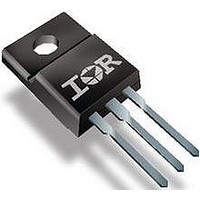
25TTS12FPPBF Vishay, 25TTS12FPPBF Datasheet - Page 4

25TTS12FPPBF
Manufacturer Part Number
25TTS12FPPBF
Description
SCRs 1200 Volt 25 Amp
Manufacturer
Vishay
Specifications of 25TTS12FPPBF
Breakover Current Ibo Max
350 A
Rated Repetitive Off-state Voltage Vdrm
1200 V
Off-state Leakage Current @ Vdrm Idrm
0.5 mA
Forward Voltage Drop
1.25 V @ 16 A
Gate Trigger Voltage (vgt)
2 V
Maximum Gate Peak Inverse Voltage
10 V
Gate Trigger Current (igt)
45 mA
Holding Current (ih Max)
100 mA
Mounting Style
Through Hole
Package / Case
TO-220
Peak Repetitive Off-state Voltage, Vdrm
1.2kV
Gate Trigger Current Max, Igt
45mA
Current It Av
16A
On State Rms Current It(rms)
25A
Peak Non Rep Surge Current Itsm 50hz
300A
Lead Free Status / RoHS Status
Lead free / RoHS Compliant
Lead Free Status / RoHS Status
Lead free / RoHS Compliant, Lead free / RoHS Compliant
Available stocks
Company
Part Number
Manufacturer
Quantity
Price
Company:
Part Number:
25TTS12FPPBF
Manufacturer:
VIR
Quantity:
2 000
Company:
Part Number:
25TTS12FPPBF
Manufacturer:
FSC
Quantity:
4 000
Document Number: 94384
25TTS12FPPbF SAFE
Bulletin I2200 rev. A 09/05
Fig. 5 - Maximum Non-Repetitive Surge Current
Number Of Equal Amplitude Half Cycle Current Pulses (N)
130
120
110
100
350
300
250
200
150
90
80
70
25
20
15
10
Fig. 3 - On-state Power Loss Characteristics
5
0
0
0
1
Fig. 1 - Current Rating Characteristics
At Any Rated Load Cond ition And With
R MS Limit
Rated V
25T T S .. S eries
Average On-state Current (A)
Average On-sta te Current (A)
180°
120°
90°
60°
30°
4
30°
5
R R M
60°
8
App lied Following S urge.
25T TS .. S eries
R
90°
thJC
10
10
120°
Conduc tion Angle
Conduc tion Angle
12
(DC) = 1.5 °C/ W
25T T S .. S eries
T = 125°C
@ 60 Hz 0.0083 s
@ 50 Hz 0.0100 s
Initial T = 125°C
J
IR
180°
15
16
J
Series
100
20
20
Fig. 6 - Maximum Non-Repetitive Surge Current
130
120
110
100
400
350
300
250
200
150
100
Fig. 4 - On-state Power Loss Characteristics
90
80
70
35
30
25
20
15
10
5
0
0.01
0
0
Fig. 2 - Current Rating Characteristics
RMS Limit
Of Cond uc tion Ma y Not Be Ma inta ined.
Maximum Non Repetitive S urge Current
25T T S .. S eries
180°
120°
DC
Average On-state Current (A)
90°
60°
30°
5
Avera ge On-sta te Current (A)
5
Versus Pulse T rain Duration. Control
30°
Pulse T ra in Duration (s)
60°
10
10
90°
25T T S .. S eries
R
thJC
120°
Rated V
No Voltage Rea pp lied
0.1
15
15
Conduc tion Period
(DC) = 1.5 °C/ W
Conduction Period
180°
www.vishay.com
25T T S .. S eries
T = 125°C
J
Initia l T = 125°C
20
20
R R M
DC
Reapp lied
J
25
25
4
30
30
1


