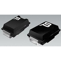
TISP5080H3BJR-S Bourns Inc., TISP5080H3BJR-S Datasheet

TISP5080H3BJR-S
Specifications of TISP5080H3BJR-S
Related parts for TISP5080H3BJR-S
TISP5080H3BJR-S Summary of contents
Page 1
Analogue Line Card and ISDN Protection - Analogue SLIC - ISDN U Interface - ISDN Power Supply 8 kV 10/700, 200 A 5/310 ITU-T K.20/21/45 rating Ion-Implanted Breakdown Region - Precise and Stable Voltage Low Voltage Overshoot under Surge V ...
Page 2
TISP5xxxH3BJ Overvoltage Protection Series Absolute Maximum Ratings Repetitive peak off-state voltage (see Note 1) Non-repetitive peak impulse current (see Notes 2, 3 and 4) 2/10 µs (GR-1089-CORE, 2/10 µs voltage wave shape) 8/20 µs (IEC 61000-4-5, ...
Page 3
TISP5xxxH3BJ Overvoltage Protection Series ° Electrical Characteristics Parameter I Breakover current (BO) V Forward voltage F V Peak forward recovery voltage FRM V On-state voltage T I Holding current H dv/dt Critical rate of rise of ...
Page 4
TISP5xxxH3BJ Overvoltage Protection Series Parameter Measurement Information V (BR)M V DRM - (BR) DRM V (BR) I (BO) V (BO) Quadrant III Switching Characteristic Figure 1. Voltage-Current Characteristic for Terminal Pair All Measurements are Referenced to the Thyristor ...
Page 5
TISP5xxxH3BJ Overvoltage Protection Series Typical Characteristics OFF-STATE CURRENT vs JUNCTION TEMPERATURE 100 10 1 0·1 0·01 0·001 - Junction Temperature - °C J Figure 2. ON-STATE AND FORWARD CURRENTS vs ON-STATE AND FORWARD VOLTAGES 200 ...
Page 6
TISP5xxxH3BJ Overvoltage Protection Series Typical Characteristics OFF-STATE CAPACITANCE vs OFF-STATE VOLTAGE 300 200 150 100 Negative Off-state Voltage - V D Figure 6. ...
Page 7
TISP5xxxH3BJ Overvoltage Protection Series Rating And Thermal Information V DERATING FACTOR DRM vs MINIMUM AMBIENT TEMPERATURE 1.00 0.99 0.98 0.97 0.96 0.95 0.94 0.93 -40 -35 -30 -25 -20 -15 - Minimum Ambient Temperature - °C AMIN ...
Page 8
TISP5xxxH3BJ Overvoltage Protection Series Deployment These devices are two terminal overvoltage protectors. They may be used either singly to limit the voltage between two points (Figure 11 multiples to limit the voltage at several points in a circuit ...
Page 9
TISP5xxxH3BJ Overvoltage Protection Series The star-connection of three TISP5xxxH3BJ protectors gives a protection circuit which has a low differential capacitance to ground (Figure 13). This example, a -100 V ISDN line is protected. In Figure 13, the circuit illustration A ...
Page 10
TISP5xxxH3BJ Overvoltage Protection Series ISDN Device Selection The ETSI Technical Report ETR 080:1993 defines several range values in terms of maximum and minimum ISDN feeding voltages. The following table shows that ranges 1 and 2 can use a TISP5110H3BJ protector ...
Page 11
TISP5xxxH3BJ Overvoltage Protection Series AC Power Testing The protector can withstand currents applied for times not exceeding those shown in Figure 8. Currents that exceed these times must be terminated or reduced to avoid protector failure. Fuses, PTC (Positive Temperature ...


