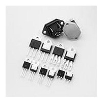
Q4025N5RP Littelfuse Inc, Q4025N5RP Datasheet - Page 8

Q4025N5RP
Manufacturer Part Number
Q4025N5RP
Description
Triacs 400V 25A 50-50-50mA
Manufacturer
Littelfuse Inc
Type
TRIACr
Datasheet
1.Q4008L4.pdf
(10 pages)
Specifications of Q4025N5RP
Rated Repetitive Off-state Voltage Vdrm
400 V
On-state Rms Current (it Rms)
25 A
Off-state Leakage Current @ Vdrm Idrm
0.1 mA
Gate Trigger Voltage (vgt)
2.5 V
Gate Trigger Current (igt)
120 mA
Holding Current (ih Max)
100 mA
Forward Voltage Drop
1.8 V
Mounting Style
SMD/SMT
Package / Case
TO-263
Maximum Operating Temperature
+ 125 C
Minimum Operating Temperature
- 40 C
Repetitive Peak Off-state Volt
400V
Off-state Voltage
400V
Hold Current
100mA
Gate Trigger Current (max)
50mA
Gate Trigger Voltage (max)
2.5V
Package Type
TO-263
Peak Repeat Off Current
100uA
Peak Surge On-state Current (max)
200A
On State Voltage(max)
1.8V
Mounting
Surface Mount
Pin Count
2 +Tab
Operating Temp Range
-40C to 125C
Operating Temperature Classification
Automotive
Lead Free Status / RoHS Status
Lead free / RoHS Compliant
Triacs
Figure E2.7 Maximum Allowable Ambient Temperature versus
Figure E2.8 On-state Current versus On-state Voltage (Typical)
Figure E2.9 On-state Current versus On-state Voltage (Typical)
http://www.littelfuse.com
+1 972-580-7777
120
100
80
60
40
25
20
10
9
8
7
6
5
4
3
2
1
0
0
0
On-state Current
(0.8 A and 1 A)
20
18
16
14
12
10
(4 A, 6 A, 8 A, and 10 A)
0.8 A TO-92
8
6
4
2
0
0.2
0
Positive or Negative Instantaneous On-state Voltage (v
Positive or Negative Instantaneous On-state Voltage (v
0.6
0.4
RMS On-state Current [I
0.6
T
T
C
C
= 25 ˚C
0.8
= 25 ˚C
1 A TO-92
0.6
0.8
0.8
1.0
6-10 A
1.0
4A
CURRENT WAVEFORM: Sinusoidal
LOAD: Resistive or Inductive
CONDUCTION ANGLE: 360
FREE AIR RATING – NO HEATSINK
1.0
TO-202 (TYPE 2 and 4)
TO-251
T (RMS)
1.2
1.2
1.2
1 A
] — Amps
1.4
TO-220 Devices and
TO-202 (Type 1 and 3)
1.4
1.4
1.6
T
T
0.8 A
) – Volts
1.6
) – Volts
˚
1.6
1.8
1.8
1.8
2.0
E2 - 8
Figure E2.10 On-state Current versus On-state Voltage (Typical)
Figure E2.11 Normalized DC Gate Trigger Current for All Quadrants
Figure E2.12 Normalized DC Gate Trigger Voltage for All Quadrants
90
80
70
60
50
40
30
20
10
0
(15 A and 25 A)
versus Case Temperature
versus Case Temperature
0
2.0
1.5
1.0
.5
0
Positive or Negative Instantaneous On-state Voltage (v
-65
4.0
3.0
2.0
1.0
-65
0.6
-40
T
C
-40
= 25 ˚C
0.8
-15
-15
25 A and 35 A Fastpak
Case Temperature (T
Case Temperature (T
1.0
+25
+25
1.2
C
Thyristor Product Catalog
+65
) – ˚C
C
) – ˚C
+65
15 A and 25 A
1.4
©2004 Littelfuse, Inc.
1.6
T
) – Volts
Data Sheets
+125
+125
1.8


