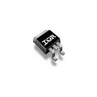
IRF9640SPBF Vishay, IRF9640SPBF Datasheet - Page 8

IRF9640SPBF
Manufacturer Part Number
IRF9640SPBF
Description
MOSFET Power P-Chan 200V 11 Amp
Manufacturer
Vishay
Type
Power MOSFETr
Specifications of IRF9640SPBF
Transistor Polarity
P-Channel
Minimum Operating Temperature
- 55 C
Configuration
Single
Resistance Drain-source Rds (on)
0.5 Ohm @ 10 V
Drain-source Breakdown Voltage
200 V
Gate-source Breakdown Voltage
+/- 20 V
Continuous Drain Current
11 A
Power Dissipation
3000 mW
Maximum Operating Temperature
+ 150 C
Mounting Style
SMD/SMT
Package / Case
D2PAK
Continuous Drain Current Id
-11A
Drain Source Voltage Vds
-200V
On Resistance Rds(on)
500mohm
Rds(on) Test Voltage Vgs
-10V
Threshold Voltage Vgs Typ
-4V
Fall Time
38 ns
Rise Time
43 ns
Number Of Elements
1
Polarity
P
Channel Mode
Enhancement
Drain-source On-res
0.5Ohm
Drain-source On-volt
200V
Gate-source Voltage (max)
±20V
Operating Temp Range
-55C to 150C
Operating Temperature Classification
Military
Mounting
Surface Mount
Pin Count
2 +Tab
Package Type
D2PAK
Lead Free Status / RoHS Status
Lead free / RoHS Compliant
Lead Free Status / RoHS Status
Lead free / RoHS Compliant, Lead free / RoHS Compliant
Available stocks
Company
Part Number
Manufacturer
Quantity
Price
Company:
Part Number:
IRF9640SPBF
Manufacturer:
IR
Quantity:
15 000
Part Number:
IRF9640SPBF
Manufacturer:
VISHAY/威世
Quantity:
20 000
TO-263AB (HIGH VOLTAGE)
Notes
1. Dimensioning and tolerancing per ASME Y14.5M-1994.
2. Dimensions are shown in millimeters (inches).
3. Dimension D and E do not include mold flash. Mold flash shall not exceed 0.127 mm (0.005") per side. These dimensions are measured at the
4. Thermal PAD contour optional within dimension E, L1, D1 and E1.
5. Dimension b1 and c1 apply to base metal only.
6. Datum A and B to be determined at datum plane H.
7. Outline conforms to JEDEC outline to TO-263AB.
Document Number: 91364
Revision: 15-Sep-08
ECN: S-82110-Rev. A, 15-Sep-08
DWG: 5970
outmost extremes of the plastic body at datum A.
DIM.
A1
b1
b2
b3
c1
c2
A
D
b
c
4
(Datum A)
MIN.
4.06
0.00
0.51
0.51
1.14
1.14
0.38
0.38
1.14
8.38
L1
L2
D
MILLIMETERS
B
B
2 x e
Lead tip
1
3
B
B
MAX.
4
4.83
0.25
0.99
0.89
1.78
1.73
0.74
0.58
1.65
9.65
E
2
C
4
3
C
2 x b
2 x b2
0.010
A
0.160
0.000
0.020
0.020
0.045
0.045
0.015
0.015
0.045
0.330
H
MIN.
5
M
INCHES
A
Plating
M
(c)
B
Section B - B and C - C
Detail A
MAX.
0.190
0.010
0.039
0.035
0.070
0.068
0.029
0.023
0.065
0.380
Scale: none
b1, b3
(b, b2)
5
± 0.004
c
A
c1
c2
Base
metal
M
B
5
B
A
A
DIM.
D1
E1
L1
L2
L3
L4
H
E
e
L
0° to 8°
L3
Gauge
plane
14.61
MIN.
6.86
9.65
6.22
1.78
4.78
MILLIMETERS
-
-
Package Information
2.54 BSC
0.25 BSC
Rotated 90° CW
L
View A - A
scale 8:1
Detail “A”
L4
E1
E
MAX.
10.67
15.88
2.79
1.65
1.78
5.28
-
-
D1
Vishay Siliconix
4
H
A1
4
0.270
0.380
0.245
0.575
0.070
0.188
MIN.
B
-
-
0.100 BSC
0.010 BSC
Seating plane
INCHES
www.vishay.com
MAX.
0.420
0.625
0.110
0.066
0.070
0.208
-
-
1


