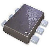
UPG2408TK-A CEL, UPG2408TK-A Datasheet - Page 3

UPG2408TK-A
Manufacturer Part Number
UPG2408TK-A
Description
RF Switch ICs .05-3GHz 2.5-5.3Volt SPDT Switch
Manufacturer
CEL
Datasheet
1.UPG2408TK-E2-A.pdf
(12 pages)
Specifications of UPG2408TK-A
Insertion Loss
0.7 dB
Maximum Operating Temperature
+ 85 C
Minimum Operating Temperature
- 45 C
Mounting Style
SMD/SMT
Number Of Switches
Single
Off Isolation (typ)
17 dB to 27 dB
Operating Frequency
3 GHz
Supply Voltage (max)
5.3 V
Supply Voltage (min)
2.5 V
Switch Configuration
SPDT
Switch Current (typ)
0.3 uA
Package / Case
MiniMold
Lead Free Status / RoHS Status
Lead free / RoHS Compliant
ELECTRICAL CHARACTERISTICS
(T
Insertion Loss 1
Insertion Loss 2
Insertion Loss 3
Insertion Loss 4
Insertion Loss 5
Isolation 1
Isolation 2
Isolation 3
Isolation 4
Isolation 5
Input Return Loss 1
Input Return Loss 2
Output Return Loss 1
Output Return Loss 2
0.1 dB Loss Compression
Input Power
Input 3rd Order Intercept Point
Switch Control Current
Switch Control Speed
A
Notes 1. DC blocking capacitors = 1 000 pF at f = 0.05 to 0.5 GHz
Caution It is necessary to use DC blocking capacitors with this device.
= +25°C, V
2. P
Note 2
The value of DC blocking capacitors should be chosen to accommodate the frequency of
operation, bandwidth, switching speed and the condition with actual board of your system. The
range of recommended DC blocking capacitor value is less than 100 pF for frequencies above 0.5
GHz, and 1 000pF for frequencies above 0.5 GHz.
linear range.
Parameter
in (0.1 dB)
cont (H)
is the measured input power level when the insertion loss increases 0.1 dB more than that of
= 3.0 V, V
cont (L)
P
Symbol
RL
RL
RL
RL
in (0.1 dB)
ISL1
ISL2
ISL3
ISL4
ISL5
L
L
L
L
L
IIP
I
t
ins
ins
ins
ins
ins
cont
SW
out
out
in
in
= 0 V, DC blocking capacitors = 56 pF, unless otherwise specified)
1
2
3
4
5
3
1
2
1
2
f = 0.05 to 0.5 GHz
f = 0.5 to 1.0 GHz
f = 1.0 to 2.0 GHz
f = 2.0 to 2.5 GHz
f = 2.5 to 3.0 GHz
f = 0.05 to 0.5 GHz
f = 0.5 to 1.0 GHz
f = 1.0 to 2.0 GHz
f = 2.0 to 2.5 GHz
f = 2.5 to 3.0 GHz
f = 0.05 to 0.5 GHz
f = 0.5 to 3.0 GHz
f = 0.05 to 0.5 GHz
f = 0.5 to 3.0 GHz
f = 2.0/2.5 GHz
f = 0.5 to 3.0 GHz
f = 0.5 to 3.0 GHz, 2 tone,
5 MHz spicing
No RF input
50% CTL to 90/10% RF
Data Sheet PG10771EJ01V0DS
Test Conditions
Note 1
Note 1
Note 1
Note 1
+27.0
MIN.
24
24
16
15
14
15
15
15
15
−
−
−
−
−
−
−
−
−
+29.0
+29.0
TYP.
0.40
0.40
0.48
0.50
0.56
+60
0.3
27
27
19
18
17
20
20
20
20
50
MAX.
0.55
0.55
0.63
0.65
0.70
500
μ
20
−
−
−
−
−
−
−
−
−
−
−
−
PG2408TK
dBm
dBm
dBm
Unit
dB
dB
dB
dB
dB
dB
dB
dB
dB
dB
dB
dB
dB
dB
μ
ns
A
3


