MB2-B-34-610-1-A24-B-C Carling Technologies, MB2-B-34-610-1-A24-B-C Datasheet
MB2-B-34-610-1-A24-B-C
Specifications of MB2-B-34-610-1-A24-B-C


Related parts for MB2-B-34-610-1-A24-B-C


MB2-B-34-610-1-A24-B-C Summary of contents
Page 1
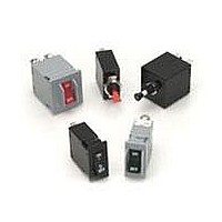
... Requires Branch Circuit Backup with a UL Listed type K-5 or RK-5 fuse rated 60 Amps maximum 18 The low cost M-Series utilizes the hydraulic magnetic principle which provides accurate and reliable circuit protection even when exposed to extremely hot and/or cold application environments. Available in a choice of rocker actuator styles and colors, push ...
Page 2
Electrical Table B: Lists UL Recognized,CSA Accepted and TUV and VDE Certified configurations and performance capabilities as a Component Supplementary Protector. NOTES FOR TABLE B 1 Polarity Sensitive 2 Available only with Special Catalog Number. Consult Factory. 3 Requires Branch ...
Page 3
... Mechanical Endurance 10,000 ON-OFF operations @ 6 per minute with rated Current and Voltage. Trip Free All M-Series Circuit Breakers will trip on overload, even when actuator is forcibly held in the ON position. Trip Indication The actuator moves positively to the OFF position when an overload causes the circuit breaker to trip. ...
Page 4
Series Actuator Poles Circuit 1 SERIES M 2 ACTUATOR 1 Handle M Paddle N Baton Push Button T Push-Pull U Push To Reset Push Button w/ Snap-In Mounting V Push-Pull ...
Page 5
M-Series Handle/Pushbutton UL489A/UL Recognized – Ordering Scheme – – Series Actuator Poles Circuit 1 SERIES M 2 ACTUATOR 1 Handle M Paddle N Baton Push Button T Push-Pull U Push To Reset ...
Page 6
– Series Actuator Poles Circuit 1 SERIES M 2 ACTUATOR 1 Non-Illuminated Two Color single color Visi-Rocker D Indicate ON A Angled E Indicate OFF B Flat 3 POLES 1 One ...
Page 7
M-Series Rocker UL489A/UL Recognized – Ordering Scheme – – Series Actuator Poles Circuit 1 SERIES M 2 ACTUATOR 1 Non-Illuminated single color A Angled B Two Color Visi-Rocker D Indicate ON E ...
Page 8
Notes: 1 All dimensions are in inches [millimeters]. 2 Tolerance ±.020 [.51] unless otherwise specified. www.carlingtech.com M-Series Handle – Circuit & Terminal Diagrams 25 ...
Page 9
M-Series Handle – Form & Fit Drawings Notes: 1 All dimensions are in inches [millimeters]. 2 Tolerance ± 0.20 [.51] unless otherwise specified. 26 www.carlingtech.com ...
Page 10
Notes: 1 All dimensions are in inches [millimeters]. 2 Tolerance ±.020 [.51] unless otherwise specified. www.carlingtech.com M-Series Handle – PC Terminal Diagrams 27 ...
Page 11
M-Series Pushbutton – Circuit & Terminal Diagrams Notes: 1 All dimensions are in inches [millimeters]. 2 Tolerance ±.020 [.51] unless otherwise specified. 28 www.carlingtech.com ...
Page 12
Notes: 1 All dimensions are in inches [millimeters]. 2 Tolerance ± 0.20 [.51] unless otherwise specified. 3 Available with Push-Pull or Push-to-Reset Actuators. www.carlingtech.com M-Series Pushbutton – Form & Fit Drawings 29 ...
Page 13
M-Series Push-Pull – PC Terminal Drawings Notes: 1 All dimensions are in inches [millimeters]. 2 Tolerance ±.020 [.51] unless otherwise specified. 30 www.carlingtech.com ...
Page 14
Notes: 1 All dimensions are in inches [millimeters]. 2 Tolerance ±.020 [.51] unless otherwise specified. 3 Schematic shown represents current trip circuit. www.carlingtech.com M-Series Rocker – Circuit & Terminal Diagrams 31 ...
Page 15
M-Series Rocker – Form & Fit Drawings Notes: 1 Dimensions apply to all variations shown. Notice that circuit breaker line & load terminal orientation on indicate OFF is opposite of indicate ON. 2 I-O, ON-OFF or dual legends available for ...
Page 16
M-Series Rocker – Supplementary Diagrams 33 ...