GNM212R61A225ME16D Murata, GNM212R61A225ME16D Datasheet - Page 3
GNM212R61A225ME16D
Manufacturer Part Number
GNM212R61A225ME16D
Description
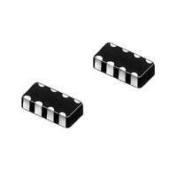
Capacitor Arrays & Networks 2 Cap Array 0805 X5R 10V 2.2uF
Manufacturer
Murata
Series
GNMr
Datasheet
1.GNM212R61A225ME16D.pdf
(4 pages)
Specifications of GNM212R61A225ME16D
Voltage Rating
10 Volts
Number Of Elements
2
Operating Temperature Range
- 55 C to + 85 C
Termination Style
SMD/SMT
Dimensions
2 mm L x 1.25 mm W x 0.2 mm H
Dissipation Factor Df
0.025
Product
Ceramic Capacitor Arrays
Capacitance
2.2 uF
Tolerance
20 %
Temperature Coefficient
X5R
Package / Case
0805
Lead Free Status / RoHS Status
Lead free / RoHS Compliant
Available stocks
Company
Part Number
Manufacturer
Quantity
Price
Company:

Part Number:
GNM212R61A225ME16D
Manufacturer:
MURATA
Quantity:
640 000
Company:
Part Number:
GNM212R61A225ME16D
Manufacturer:
MURATA
Quantity:
240 000


No.
15
16
17
GNM Series Specifications and Test Method (1)
Continued from the preceding page.
Temperature
Cycle
Humidity Steady
State
Humidity Load
Item
Appearance
Capacitance
Change
Q/D.F.
I.R.
Dielectric
Strength
Appearance
Capacitance
Change
Q/D.F.
I.R.
Dielectric
Strength
Appearance
Capacitance
Change
Q/D.F.
I.R.
Dielectric
Strength
The measured and observed characteristics should satisfy the
specifications in the following table.
No marking defects
Within T2.5%
(Whichever is
larger)
30pF min.: QU1000
30pF max.:
C:Nominal
More than 10,000MΩ or 500Ω · F (Whichever is smaller)
No failure
The measured and observed characteristics should satisfy the
specifications in the following table.
No marking defects
Within T5%
(Whichever is
larger)
30pF and over:
10pF and over,
30pF and below:
10pF and below:
C: Nominal
More than 1,000MΩ or 50Ω · F (Whichever is smaller)
No failure
The measured and observed characteristics should satisfy the
specifications in the following table.
No marking defects
Within T7.5%
(Whichever is
larger)
30pF and over:
30pF and below:
C: Nominal
More than 500MΩ or 25Ω · F (Whichever is smaller)
No failure
Compensating Type
Capacitance (pF)
Capacitance (pF)
Capacitance (pF)
Temperature
QU100+10C/3
QU275+5C/2
or T0.25pF
QU400+20C
or T0.75pF
QU200+10C
or T0.5pF
QU350
QU200
R7, R6: Within T7.5%
R7, R6: Within T12.5%
R7, R6: Within T12.5%
R7, R6
R7, R6
R7, R6
Char.
Char.
Char.
Specifications
25V min.
25V min.
25V min.
0.025
max.
max.
max.
0.05
0.05
High Dielectric Type
0.035
max.
16V
max.
0.05
max.
0.05
16V
16V
0.035
max.
10V
10V/6.3V
10V/6.3V
max.
0.05
max.
0.05
max.
6.3V
0.05
Fix the capacitor to the supporting jig in the same manner and
under the same conditions as (10). Perform the five cycles
according to the four heat treatments listed in the following
table. Let sit for 24T2 hours (temperature compensating type)
or 48T4 hours (high dielectric constant type) at room
temperature, then measure.
• Initial measurement for high dielectric constant type
Sit the capacitor at 40T2°C and 90 to 95% humidity for 500T12
hours.
Remove and let sit for 24T2 hours at room temperature, then
measure.
Apply the rated voltage at 40T2°C and 90 to 95% humidity for
500T12 hours.
Remove and let sit for 24T2 hours at room temperature, then
measure.
The charge/discharge current is less than 50mA.
Perform a heat treatment at 150+0/-10°C for one hour and
then let sit for 24T2 hours at room temperature.
Perform the initial measurement.
Temp. (°C)
Time (min.)
Step
Temp. +0/–3
Operating
30±3
Min.
1
Test Method
Temp.
Room
2 to 3
Continued on the following page.
2
Temp. +3/–0
Operating
Max.
30±3
3
Temp.
Room
2 to 3
4
Related parts for GNM212R61A225ME16D
Image
Part Number
Description
Manufacturer
Datasheet
Request
R

Part Number:
Description:
Murata Microblower 20x20 DCDC Driver Board - Samples Only
Manufacturer:
Murata
Part Number:
Description:
357-036-542-201 CARDEDGE 36POS DL .156 BLK LOPRO
Manufacturer:
Murata
Datasheet:
Part Number:
Description:
Manufacturer:
Murata
Datasheet:
Part Number:
Description:
Manufacturer:
Murata
Datasheet:
Part Number:
Description:
Manufacturer:
Murata
Datasheet:
Part Number:
Description:
Manufacturer:
Murata
Datasheet:
Part Number:
Description:
Manufacturer:
Murata
Datasheet:
Part Number:
Description:
Manufacturer:
Murata
Datasheet:
Part Number:
Description:
Manufacturer:
Murata
Datasheet:
Part Number:
Description:
BLM21BD751SN1On-Board Type (DC) EMI Suppression Filters
Manufacturer:
Murata
Datasheet:
Part Number:
Description:
BLM15AG100SN1On-Board Type (DC) EMI Suppression Filters
Manufacturer:
Murata
Datasheet:
Part Number:
Description:
NFE31PT222Z1E9On-Board Type (DC) EMI Suppression Filters
Manufacturer:
Murata
Datasheet:
Part Number:
Description:
Chip Coil
Manufacturer:
Murata
Datasheet:
Part Number:
Description:
Chip Coil
Manufacturer:
Murata
Datasheet: