97-3057-1008-1 Amphenol Industrial Operations, 97-3057-1008-1 Datasheet - Page 23
97-3057-1008-1
Manufacturer Part Number
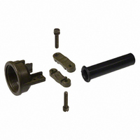
97-3057-1008-1
Description
CABLE CLAMP+BUSHING 16,16S
Manufacturer
Amphenol Industrial Operations
Series
MIL-5015, 97r
Specifications of 97-3057-1008-1
Cable Opening
0.563" (14.27mm)
Shell Size - Insert
16, 16S
Thread Size
7/8-20
Features
Bushing
Connector Type
Circular Industrial
Connector Shell Size
16 / 16S
Strain Relief Material
Zinc Alloy
Cable Diameter Max
14.27mm
Body Material
Zinc Alloy
Cable Diameter
14.27mm
For Use With
97-3106A-16S-5P - CONN PLUG 3POS STRAIGHT W/PIN97-3106A-16-10S - CONN PLUG 3POS STRAIGHT W/SKT97-3106A-16-10P - CONN PLUG 3POS STRAIGHT W/PIN97-3101A-16S-1S - CONN RCPT 7POS CABLE MNT W/SKT97-3101A-16S-1P - CONN RCPT 7POS CABLE MNT W/PIN97-3106A-16-11P - CONN PLUG 2POS STRAIGHT W/PINS97-3100A-16S-1S - CONN RECP WALL MOUNT 7 POS97-3106A-16S-8S - CONN PLUG 5POS W/SOCKETS97-3106A-16S-8P - CONN PLUG 5POS W/PINS97-3106A-16S-1S - CONN PLUG 7POS W/SOCKETS97-3106A-16S-1P - CONN PLUG 7POS W/PINS
Lead Free Status / RoHS Status
Contains lead / RoHS non-compliant
Diameter
-
Lead Free Status / RoHS Status
Contains lead / RoHS non-compliant


97 series crimp type
specifications, insert availability,
alternate insert positioning
Specifications
Standard shell finish - clear chromate over cadmium plate
(optional plating available, see how to order page 27).
Inserts - molded of a 94V-O Underwriters Laboratory rated
material.
Contacts - copper alloy formed, silver plated (gold plating is
also available, see how to order page 28).
Wire sizes - 12 AWG through 30 AWG.
All constructions perform satisfactorily from –55°C to
+125°C ( –67°F to +257°F).
Insert Availability
10SL-3
10SL-4
12S-3
14S-1
14S-2
14S-5
14S-7
16S-1
16S-8
18-1
18-4
18-11
18-12
18-19
18-20
20-4
20-7
20-27
20-29
22-14
24-2
28-11
28-12
28-20
28-21
32-414
36-10
Number
Insert
Contacts
Total
10
10
14
17
19
22
26
14
37
52
48
3
2
2
3
4
5
3
7
5
4
5
6
5
4
8
7
1/16
1/16
1/16
1/16
1/16
1/16
1/16
1/16
1/8
1/16
1/16
1/16
1/16
1/8
1/8
1/16
1/16
1/16
1/16
1/8
1/16
1/16
1/16
1/16
1/16
1/16
Inches
Mechanical
Spacing
1.57
1.57
1.57
1.57
1.57
1.57
1.57
1.57
3.18
1.57
1.57
1.57
1.57
3.18
3.18
1.57
1.57
1.57
1.57
3.18
1.57
1.57
1.57
1.57
1.57
1.57
mm
Service
INST.
INST.
INST.
Rating
D
D
D
D
A
A
A
A
A
A
A
A
A
A
A
A
A
A
A
A
A
A
A
A
A
A
Contact Size
10
12
5
4
7
4
10
14
17
19
18
26
37
52
48
16
3
2
2
3
4
5
3
7
5
4
6
4
6
5
4
4
4
21
Alternate Insert Positioning
* Rotates opposite above illustration.
Arrangement
12S-3
14S-2
14S-5
14S-7
16S-1
16S-8
18-1
18-4
18-11
18-12
18-19
18-20
20-4
20-7
20-27
20-29
22-14
24-2
28-9
28-11
28-12
28-20
28-21
32-8
32-414*
36-10
Insert
FRONT FACE OF PIN INSERT
80*
70
90
80
70
35
80
90
45
80
35
80
80
80
80
80
90
80
80
80
80
W
–
–
–
–
–
W
X
110*
145
120
110
180
170
145
110
170
120
180
110
110
110
110
110
180
110
110
125
125
–
–
–
–
–
C L
X
normal
Degrees
Y
Z
250*
215
240
270
265
215
250
265
240
270
250
250
250
250
250
270
250
250
235
235
–
–
–
–
–
–
Y
280*
290
280
290
325
280
280
325
280
280
280
280
280
280
280
280
280
–
–
–
–
–
–
–
–
–
Z
Related parts for 97-3057-1008-1
Image
Part Number
Description
Manufacturer
Datasheet
Request
R

Part Number:
Description:
CABLE CLAMP+BUSHING 18
Manufacturer:
Amphenol Industrial Operations
Datasheet:

Part Number:
Description:
CABLE CLAMP+BUSHING 24,28
Manufacturer:
Amphenol Industrial Operations
Datasheet:

Part Number:
Description:
CABLE CLAMP+BUSHING 20,22
Manufacturer:
Amphenol Industrial Operations
Datasheet:

Part Number:
Description:
CABLE CLAMP 18 5/8OD
Manufacturer:
Amphenol Industrial Operations
Datasheet:

Part Number:
Description:
CABLE CLAMP 24,28 15/16OD
Manufacturer:
Amphenol Industrial Operations
Datasheet:

Part Number:
Description:
JAM NUT CONN, RCPT, SIZE 9, 6POS, PANEL
Manufacturer:
Amphenol Industrial Operations
Datasheet:

Part Number:
Description:
PT 41C 41#20 PIN RECP
Manufacturer:
Amphenol Industrial Operations
Part Number:
Description:
PT 41C 41#20 SKT RECP
Manufacturer:
Amphenol Industrial Operations