UTG18-AC Souriau Connection Technology, UTG18-AC Datasheet - Page 101
UTG18-AC
Manufacturer Part Number
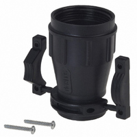
UTG18-AC
Description
CABLE CLAMP W/STRAIN RELIEF #18
Manufacturer
Souriau Connection Technology
Series
Trim Trio® UTGr
Type
Clampr
Specifications of UTG18-AC
Cable Opening
0.197" ~ 0.748" (5.00mm ~ 19.00 mm)
Shell Size - Insert
18
Thread Size
1 1/16-18
Features
Strain Relief
Operating Temp Range
-55C to 125C
Product Length (mm)
50mm
Lead Free Status / RoHS Status
Lead free / RoHS Compliant
Diameter
-
Lead Free Status / RoHS Status
Compliant, Lead free / RoHS Compliant
Other names
SOU1127
UTG1-8AC
UTG18AC
UTG1-8AC
UTG18AC


Current ratings for multi-contact connectors
Choice of right connector -
contact combination.
The choice of a Trim Trio connector in
combination with a Trim Trio contact is
essential and different for any application
There is considerable misunderstanding in
the field on current carrying capabilities for
the various contacts in the TrimTrio
programme.
The intention of this part is to give guidance
how to interprete the given current ratings in
general and how to calculate them for
particular applications.
The information given is based upon existing
MIL specifications such as:
MIL-C-26482, MIL-C-8384,
MIL-T-7928, MIL-W-5086,
MIL-W-5088, MIL-W-16878, etc. and in
conjunction with long field practice.
Current carrying capabilities
Trim Trio contacts are designed to carry a
specific current, in accordance with the
applicable specification.
This specification will be defined by
following variables:
• Connector size
The more contacts in a connector, the less
current per contact can be loaded.
• Wire size (see table 1)
The cross section will determine the internal
resistance and temperature rise for a given
current.
-Table 1 gives the current ratings for the
various wire sizes commonly used with Trim
Trio contacts.
• Current rating (see table 2)
The current load for a given application will
generate heat.
- Table 2 gives the maximum current
carrying capacity of most of the Trim Trio
contacts, the maximum operating current
and the recommended continuous current.
• Ambient temperature
The combination of the connector size, the
wire size and the current rating will generate
a temperature rise.
This temperature rise + a given ambient
temperature may not exeed the maximum
operating temperature of the connector
material (see performance characteristics for
each connector family).
98
Contacts
Table 1 - Current carrying capabilities per wire size
Table 2 - Current carrying capabilities per contact type
• Max. current carrying capacity
• Max. operating current
• Recommended continuous current
What do these values mean in practice ?
• Max current carrying capacity
of a contact is defined by the conducting
section of the contact in its smallest area.
The listed values are obtained from several
tests in laboratories under room conditions
(21°C). The contact is considered to be in
free air.
• Max operating current
is the current with which the contacts can
be energized during a longer or shorter
period, without deteriorating and depending
on working conditions.
These are dissipated heat, cooling
provisions, ambient temperature, insulation
material, etc.
AWG
size
26
24
22
20
18
16
14
16
20
wire size
pin dia.
1.6 mm
1.0 mm
.062*
.040*
mm
0.13
0.20
0.32
0.52
0.82
1.30
2.10
2
SM-W / SC-W
machined
stamped
stamped
wire dia.
RM / RC
SM / SC
2 piece
2 piece
Amp.
type
0.40
0.51
0.64
0.81
1.02
1.29
1.63
mm
• Recommended continuous current
can be applied for all normal cases and
working conditions. The values include a
safety margin. However, there are
restrictions in the application of the given
values. The most important restriction is the
used wire, its sectional area, insulation
temperature range, as well as wires in
bundles.
Military specifications require that for a
cable bundle of 15 conductors or more, the
bundle shall not carry more than 20% of the
total carrying capacity of the bundle.
In smaller bundles, the allowable percentage
of total current may be increased as the
bundle approaches the single wire condition.
This percentage of increase in total current
carrying capacity of the bundle is 6% for
each conductor less than 15 in a bundle.
max. curr.
max.curr.
carrying
carying
Amp.
Amp.
4.5
11
16
22
32
22
22
11
3
9
max. oper-
ating curr.
ating curr.
max.oper-
Amp.
Amp.
7.5
7.5
10
13
17
13
13
2
3
5
cont. curr.
cont. curr.
recomm.
recomm.
Amp.
7.5
10
13
10
10
1
2
3
5
5
Related parts for UTG18-AC
Image
Part Number
Description
Manufacturer
Datasheet
Request
R

Part Number:
Description:
CONN SEALING FOR WALL RCPT #22
Manufacturer:
Souriau Connection Technology
Part Number:
Description:
CONN SEALING FOR WALL RCPT #14
Manufacturer:
Souriau Connection Technology
Datasheet:

Part Number:
Description:
CONN RCPT SEALING CAP SIZE 10
Manufacturer:
Souriau Connection Technology
Datasheet:

Part Number:
Description:
CONN RCPT SEALING CAP SIZE 14
Manufacturer:
Souriau Connection Technology
Datasheet:

Part Number:
Description:
CONN STRAIN RELIEF 12POS
Manufacturer:
Souriau Connection Technology
Datasheet:

Part Number:
Description:
D38999 Series 3
Manufacturer:
Souriau Connection Technology
Datasheet: