MKP1840447635 Vishay, MKP1840447635 Datasheet
MKP1840447635
Specifications of MKP1840447635


Related parts for MKP1840447635


MKP1840447635 Summary of contents
Page 1
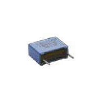
... Maximum pulse rise time d 160 VDC 250 VDC — — 240 300 175 220 100 125 values can be permitted For technical questions, contact dc-film@vishay.com MKP 1840 Vishay Roederstein Dimensions in millimeters L W Max. Max. 0.4 Ød W < (typical value 1 0 ...
Page 2
... EXAMPLE (mm) S* MKP 1840-310-405-D S* MKP 1840-310-405-G 350 MKP 1840-310-405-F 350 MKP 1840-310-405-W 500 MKP 1840-522-255-V L* MKP 1840-522-255-G — MKP 1840-522-255 For technical questions, contact dc-film@vishay.com 1 >1 — — — VOLTAGE VOLTAGE CODE 40 CODE 63 400 VDC/ 630 VDC/ 220 VAC* 250 VAC* ...
Page 3
... Permissible AC Voltage versus Frequency 5 Capacitance 100 [Hz] Permissible AC Voltage versus Frequency Capacitance 0.001 0.01 f [Hz] Impedance versus Frequency (f) (Lead length 2.0mm) For technical questions, contact dc-film@vishay.com MKP 1840 Vishay Roederstein Capacitance in F 160 VDC Capacitance in F 400 VDC 0 [Hz [Hz 100 [MHz] www.vishay.com 73 ...