BLM18PG121SN1D Murata, BLM18PG121SN1D Datasheet - Page 107
BLM18PG121SN1D
Manufacturer Part Number
BLM18PG121SN1D
Description
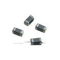
EMI/RFI Suppressors & Ferrites 0603 120 OHM
Manufacturer
Murata
Specifications of BLM18PG121SN1D
Shielding
Unshielded
Test Frequency
100 MHz
Product
Chip Ferrite Beads
Impedance
120 Ohms
Tolerance
25 %
Maximum Dc Current
2000 mAmps
Maximum Dc Resistance
0.05 Ohms
Operating Temperature Range
- 55 C to + 125 C
Package / Case
0603 (1608 metric)
Termination Style
SMD/SMT
Dc Resistance Max
0.05ohm
Dc Current Rating
2A
Ferrite Mounting
SMD
Ferrite Case Style
0603
Inductor Case Style
0603
No. Of Pins
2
Core Material
Ferrite
Resistance
0.05ohm
Rohs Compliant
Yes
Operating Temperature Min
-55°C
Operating Temperature Max
+125°C
Lead Free Status / RoHS Status
Lead free / RoHS Compliant
Available stocks
Company
Part Number
Manufacturer
Quantity
Price
Company:

Part Number:
BLM18PG121SN1D
Manufacturer:
KEMET
Quantity:
500 000
Company:
Part Number:
BLM18PG121SN1D
Manufacturer:
Murata
Quantity:
76 000
Part Number:
BLM18PG121SN1D
Manufacturer:
MURATA/村田
Quantity:
20 000


(Part Number)
!Note
LC Combined (1)
• Please read rating and !CAUTION (for storage, operating, rating, soldering, mounting and handling) in this catalog to prevent smoking and/or burning, etc.
• This catalog has only typical specifications because there is no space for detailed specifications. Therefore, please review our product specifications or consult the approval sheet for product specifications before ordering.
qProduct ID
wStructure
eDimensions (LgW)
rFeatures
tCut-off Frequency (NFL/NFW Series)
Expressed by three figures. The unit is in hertz (Hz). The first and
second figures are significant digits, and the third figure
expresses the number of zeros which follow the two figures.
tCapacitance (NFE Series)
Expressed by three figures. The unit is in pico-farad (pF). The first
and second figures are significant digits, and the third figure
expresses the number of zeros which follow the two figures.
oPackaging
NF
q
Product ID
Code
Code
Code
Code
NF
SP
ST
PT
18
21
31
61
W
E
K
B
D
L
L
w
L
e
18
ST
Dimensions (LgW)
r
Embossed Taping (ø330mm Reel)
Embossed Taping (ø180mm Reel)
Wire Wound, LC Combined Type
2.0g1.25mm
Maltilayer, LC Combined Type
1.6g0.8mm
3.2g1.6mm
6.8g1.6mm
Paper Taping (ø180mm Reel)
Block, LC Combined Type
T Circuit for Large Current
T Circuit for Signal Lines
107
Circuit for Signal Lines
t
Chip EMIFILr
Packaging
Structure
Features
Bulk
y
X
1C
u
i o
3
0603
0805
1206
2606
EIA
L
yCharacteristics (NFL/NFW Series)
yCharacteristics (NFE Series)
uRated Voltage
iElectrode
NFW31/NFE
NFW31/NFE
NFL18/NFL21/NFE
NFL18/NFL21
Code
Code
Code
Code
3/7
1A
1C
1E
1H
2A
X
B
C
D
E
R
U
F
Z
4
9
Capacitance Change (Temperature Characteristics)
NFp Chip EMIFILr
Lead Free Solder Coating
Series
Sn Plating
Electrode
Others
+20/-30%, +22/-33%
+20/-55%, +22/-56%
+30/-80%, +22/-82%
Cut-off Frequency
-750 120ppm/ ˚C
Characteristics
Rated Voltage
20%, 22%
Other
100V
10V
16V
25V
50V
10%
15%
Part Numbering
Series
NFW
NFL
NFE
105
Mar.28,2011
C31E.pdf
Related parts for BLM18PG121SN1D
Image
Part Number
Description
Manufacturer
Datasheet
Request
R

Part Number:
Description:
Murata Microblower 20x20 DCDC Driver Board - Samples Only
Manufacturer:
Murata
Part Number:
Description:
357-036-542-201 CARDEDGE 36POS DL .156 BLK LOPRO
Manufacturer:
Murata
Datasheet:
Part Number:
Description:
Manufacturer:
Murata
Datasheet:
Part Number:
Description:
Manufacturer:
Murata
Datasheet:
Part Number:
Description:
Manufacturer:
Murata
Datasheet:
Part Number:
Description:
Manufacturer:
Murata
Datasheet:
Part Number:
Description:
Manufacturer:
Murata
Datasheet:
Part Number:
Description:
Manufacturer:
Murata
Datasheet:
Part Number:
Description:
Manufacturer:
Murata
Datasheet:
Part Number:
Description:
BLM21BD751SN1On-Board Type (DC) EMI Suppression Filters
Manufacturer:
Murata
Datasheet:
Part Number:
Description:
BLM15AG100SN1On-Board Type (DC) EMI Suppression Filters
Manufacturer:
Murata
Datasheet:
Part Number:
Description:
NFE31PT222Z1E9On-Board Type (DC) EMI Suppression Filters
Manufacturer:
Murata
Datasheet:
Part Number:
Description:
Chip Coil
Manufacturer:
Murata
Datasheet:
Part Number:
Description:
Chip Coil
Manufacturer:
Murata
Datasheet: