BLM21BD222TN1D Murata, BLM21BD222TN1D Datasheet - Page 182
BLM21BD222TN1D
Manufacturer Part Number
BLM21BD222TN1D
Description
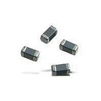
EMI/RFI Suppressors & Ferrites 0805 2.2Kohms HiSpd Signal Line Tape
Manufacturer
Murata
Series
BLM Br
Datasheets
1.BLM18EG121SN1-D.pdf
(209 pages)
2.BLM21BB471SN1D.pdf
(6 pages)
3.BLM21BD222TN1D.pdf
(6 pages)
Specifications of BLM21BD222TN1D
Shielding
Unshielded
Test Frequency
100 MHz
Product
Chip Ferrite Beads
Impedance
2.2 KOhms
Tolerance
25 %
Maximum Dc Current
200 mAmps
Maximum Dc Resistance
0.6 Ohms
Operating Temperature Range
- 55 C to + 125 C
Package / Case
0805 (2012 metric)
Termination Style
SMD/SMT
Dc Resistance Max
0.6ohm
Dc Current Rating
200mA
Ferrite Mounting
SMD
Ferrite Case Style
0805
Inductor Case Style
0805
No. Of Pins
2
Core Material
Ferrite
Resistance
0.6ohm
Rohs Compliant
Yes
Operating Temperature Min
-55°C
Operating Temperature Max
+125°C
Dc
1121
Lead Free Status / RoHS Status
Lead free / RoHS Compliant
Available stocks
Company
Part Number
Manufacturer
Quantity
Price
Company:

Part Number:
BLM21BD222TN1D
Manufacturer:
MURATA
Quantity:
240 000
Part Number:
BLM21BD222TN1D
Manufacturer:
MURATA/村田
Quantity:
20 000


PL
o
!Note
180
1. Standard Land Pattern Dimensions
PLT10H
2. Solder Paste Printing and Adhesive Application
PLT10H
PCB Warping
When reflow soldering the
coils, the printing must be conducted in accordance with
the following cream solder printing conditions.
If too much solder is applied, the chip will be prone to
damage by mechanical and thermal stress from the PCB
and may crack.
Standard land dimensions should be used for resist and
copper foil patterns.
PCB should be designed so that products are not
subjected to the mechanical stress caused by warping
the board.
• Please read rating and !CAUTION (for storage, operating, rating, soldering, mounting and handling) in this catalog to prevent smoking and/or burning, etc.
• This catalog has only typical specifications because there is no space for detailed specifications. Therefore, please review our product specifications or consult the approval sheet for product specifications before ordering.
Series
p
Chip Common Mode Choke Coil
oGuideline of solder paste thickness:
*Solderability is subject to reflow conditions and thermal conductivity. Please make sure that your
oReflow Soldering
product has been evaluated in view of your specifications with our product being mounted to your
product.
150-200 m: PLT10H
For the solder paste printing pattern, use standard land dimensions.
chip common mode choke
4.0
PLT10H
8.0
4.0
Solder Paste Printing
Copper Foil Pattern
Copper Foil Pattern + Resist
Resist
When flow soldering the
apply the adhesive in accordance with the following
conditions.
If too much adhesive is applied, then it may overflow into
the land or termination areas and yield poor solderability.
In contrast, if insufficient adhesive is applied, or if the
adhesive is not sufficiently hardened, then the chip may
become detached during flow soldering process.
Soldering and Mounting
Products should be located in the sideways direction
(Length: a<b) to the mechanical stress.
Poor example
chip common mode choke
Good example
b
a
(in mm)
coils,
Mar.28,2011
C31E.pdf
Related parts for BLM21BD222TN1D
Image
Part Number
Description
Manufacturer
Datasheet
Request
R

Part Number:
Description:
Murata Microblower 20x20 DCDC Driver Board - Samples Only
Manufacturer:
Murata
Part Number:
Description:
357-036-542-201 CARDEDGE 36POS DL .156 BLK LOPRO
Manufacturer:
Murata
Datasheet:
Part Number:
Description:
Manufacturer:
Murata
Datasheet:
Part Number:
Description:
Manufacturer:
Murata
Datasheet:
Part Number:
Description:
Manufacturer:
Murata
Datasheet:
Part Number:
Description:
Manufacturer:
Murata
Datasheet:
Part Number:
Description:
Manufacturer:
Murata
Datasheet:
Part Number:
Description:
Manufacturer:
Murata
Datasheet:
Part Number:
Description:
Manufacturer:
Murata
Datasheet:
Part Number:
Description:
BLM21BD751SN1On-Board Type (DC) EMI Suppression Filters
Manufacturer:
Murata
Datasheet:
Part Number:
Description:
BLM15AG100SN1On-Board Type (DC) EMI Suppression Filters
Manufacturer:
Murata
Datasheet:
Part Number:
Description:
NFE31PT222Z1E9On-Board Type (DC) EMI Suppression Filters
Manufacturer:
Murata
Datasheet:
Part Number:
Description:
Chip Coil
Manufacturer:
Murata
Datasheet:
Part Number:
Description:
Chip Coil
Manufacturer:
Murata
Datasheet: