Output ................................................................................................................................................................................................................2-bit gray code
Closed Circuit Resistance ..............................................................................................................................................................................3 ohms maximum
Contact Rating ....................................................................................................................................................................................................1 mA @ 5 VDC
Insulation Resistance ........................................................................................................................................................................100 megohms @ 250 VDC
Dielectric Withstanding Voltage
Electrical Travel ........................................................................................................................................................................................................Continuous
Contact Bounce (15 RPM) ..............................................................................................................................................................................5.0 ms maximum
RPM (Operating) ....................................................................................................................................................................................................60 maximum
Operating Temperature Range ..........................................................................................................................................-30 °C to +70 °C (-22 °F to +158 °F)
Storage Temperature Range ............................................................................................................................................-40 °C to +85 °C (-40 °F to +185 °F)
Humidity....................................................................................................................................................................MIL-STD-202, Method 103B, Condition B
Vibration ..............................................................................................................................................................................................................................30 G
Shock ................................................................................................................................................................................................................................100 G
Rotational Life........................................................................................................................................................................................30,000 cycles minimum
Switch Life ............................................................................................................................................................................................20,000 cycles minimum
IP Rating ..............................................................................................................................................................................................................................IP 40
Mechanical Angle ............................................................................................................................................................................................360 ° continuous
Torque
Shaft Side Load (Static) ..................................................................................................................................................................2.04 kgf (4.5 lbs.) minimum
Weight ................................................................................................................................................................................................5 gm (0.17 oz.) maximum
Terminals ....................................................................................................................................................................................Printed circuit board terminals
Hardware ........................................................................................................................One flat washer and one mounting nut supplied with each encoder.
Switch Type ......................................................................................................................................................................Contact Push ON Momentary SPST
Power Rating (Resistive Load) ........................................................................................................................................................................10 mA at 5 V DC
Switch Travel ..........................................................................................................................................................................................................0.5 ± 0.2 mm
Switch Actuation Force ..........................................................................................................................................................610 ± 306 gf (8.47 ± 4.24 oz.-in.)
Model
Terminal Configuration
Detent Option
Standard Shaft Length
Shaft Style
Switch Configuration
Resolution
* Metal knurled shaft with no switch is available in 15, 20 and 30 mm shaft lengths.
Electrical Characteristics
Environmental Characteristics
Mechanical Characteristics
Switch Characteristics
How To Order
Sea Level ..................................................................................................................................................................................................300 VAC minimum
Contact Bounce ..................................................................................................................................................10~55~10 Hz / 1 min. / Amplitude 1.5 mm
Running ..........................................................................................................................................................................50 to 200 gf.cm (0.68 to 2.7 oz.-in.)
Mounting ........................................................................................................................................................................10.2 kgf.cm (8.83 lb.-in.) maximum
Soldering Condition
4 =
0 =
1 =
2 =
15 = 15.0 mm
20 = 20.0 mm
25 = 25.0 mm
30 = 30.0 mm
F =
K =
S =
N =
0012 = 12 Pulses per 360 ° Rotation
0018 = 18 Pulses per 360 ° Rotation
0024 = 24 Pulses per 360 ° Rotation
Metal knurled shaft with push momentary switch is available in 15 and 20 mm shaft lengths.
Wave Soldering........................................................................................Sn95.5/Ag2.8/Cu0.7 solder with no-clean flux: 260 °C max. for 3-5 seconds
Hand Soldering ....................................................................................................................................................................................Not recommended
PC Pin Horizontal/Rear Facing
No Detents (12, 18, 24 pulses)
18 Detents (18 pulses)
24 Detents (12, 24 pulses)
Metal Flatted Shaft
Metal Knurled Shaft*
Push Momentary Switch
No Switch
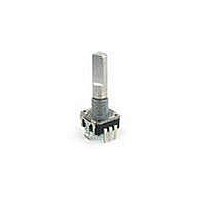
PEC11 Series - 12 mm Incremental Encoder
Features
Push switch option
Compact, rugged design
High reliability
Metal bushing/shaft
PEC11 - 4 0 20 F - S 0012
Customers should verify actual device performance in their specific applications.
*RoHS Directive 2002/95/EC Jan 27 2003 including Annex
Applications
Level control, tuning and timer settings in:
Quadrature Output Table
Audio-visual equipment
Consumer electric appliances
Radios
Musical instrumentation
Communications equipment
Specifications are subject to change without notice.
A Signal
B Signal
CW
OFF
D
ON