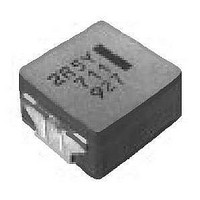
ETQ-P5M3R3YFC Panasonic, ETQ-P5M3R3YFC Datasheet - Page 3

ETQ-P5M3R3YFC
Manufacturer Part Number
ETQ-P5M3R3YFC
Description
Power Inductors Choke Coils 3.3 uH 20% 5.1 Amps SMD/SMT
Manufacturer
Panasonic
Datasheet
1.ETQ-P5M470YFM.pdf
(6 pages)
Specifications of ETQ-P5M3R3YFC
Product
Choke Coils
Test Frequency
100 KHz
Inductance
3.3 uH
Tolerance
20 %
Maximum Dc Current
5.1 Amps
Maximum Dc Resistance
7.1 mOhms
Dimensions
10 mm W x 10.7 mm L x 5.4 mm H
Shielding
Unshielded
Operating Temperature Range
- 40 C to + 150 C
Termination Style
SMD/SMT
Lead Free Status / RoHS Status
Lead free / RoHS Compliant
2. PCC-M0854M/PCC-M0850M Series (ETQP5M
■
(
(
(
■
● Inductance vs DC Current
● Case Temperature vs DC Current
✽ Our temperature rise is specifi ed with measurement of single layer PWB(condition A). Please refer to temperature rise curve V.S. current for the rated current
Design and specifi cations are each subject to change without notice. Ask factory for the current technical specifi cations before purchase and/or use.
Should a safety concern arise regarding this product, please be sure to contact us immediately.
✽
✽
✽
[8.5 8.0 5.4(mm)]
[8.5 8.0 5.0(mm)]
1) Inductance is measured at 100 kHz.
2) Rated current defi nes actual value of DC current which is case temperature rise becomes 15 K.
3) Reference current defi nes actual value of DC current which is case temperature rise becomes 40 K.
(∆T=15K) and Reference value (∆T=40K). and when four layer PWB (condition B) is used, temperature rise is different from single layer PWB(conditionA).
Even we specify the rated current at our condition, the actual temperature rise of PCC may have different result due to thermal
dissipation condition. We recommend customers to measure PCC temperature rise at application to confi rm it.
Standard Parts
Performance Characteristics (Ref er ence)
PCC-M0854M
PCC-M0850M
120
100
3.0
2.5
2.0
1.5
1.0
0.5
0.0
80
60
40
20
80
70
60
50
40
30
20
10
80
70
60
50
40
30
20
10
0
0
0
Series
0
0
0 2 4 6 8 10 12 14 16 18
0
0.4 0.8 1.2 1.6 2.0 2.4
ETQP5M2R5YFK
ETQP5M101YGK
ETQP5M101YGK
5
PWB condition A
PWB condition B
ETQP5M2R5YFK
PWB condition A
PWB condition B
1
10
2
I
I
I
I
DC
DC
DC
DC
15
(A)
(A)
(A)
(A)
3
ETQP5M101YGK
ETQP5M2R5YFK
ETQP5M220YFK
ETQP5M470YFK
20
Part No.
4
25
30
5
✽
PWB condition A : FR4, single layer PWB, t=1.6mm ✽our specifi cation
PWB condition B : FR4, four layer PWB, t=1.6mm
(µH)
2.45
100
L0
22
48
Inductance
80
70
60
50
40
30
20
10
25
20
15
10
0
5
0
0 0.5 1.0 1.5 2.0 2.5 3.0 3.5 4.0
0
ETQP5M220YFK
PWB condition A
PWB condition B
ETQP5M220YFK
2
Tolerance
– 173 –
±20
±20
±20
±20
✽1
(%)
4
I
YFK/ETQP5M
I
DC
DC
(A)
(A)
6
Rated current Reference current
8
T=15K
0.74
4.5
1.6
1.1
(A)
10
✽2
YGK)
T=40K
(A)
7.5
2.6
1.8
1.2
80
70
60
50
40
30
20
10
60
50
40
30
20
10
0
0
✽3
0
0
ETQP5M470YFK
1
PWB condition A
PWB condition B
ETQP5M470YFK
2
(m )
Typ.
125
302
7.6
63
2
DC resistance
I
I
DC
DC
3
4
Choke Coils
(A)
(A)
4
Tolerance
00
6
5
±10
±10
±10
±10
(%)
Sep. 2010
6
8


