B82498B3820J EPCOS Inc, B82498B3820J Datasheet - Page 11
B82498B3820J
Manufacturer Part Number
B82498B3820J
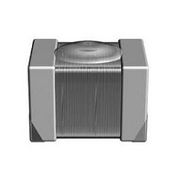
Description
RF Inductors 82nH 150MHz 390mA 5%
Manufacturer
EPCOS Inc
Specifications of B82498B3820J
Dimensions
1.2 mm W x 2.2 mm L x 1.4 mm H
Test Frequency
150 MHz
Inductance
82 nH
Tolerance
5 %
Maximum Dc Current
390 mA
Maximum Dc Resistance
0.21 Ohms
Self Resonant Frequency
1.43 GHz
Q Minimum
40
Operating Temperature Range
- 55 C to + 125 C
Termination Style
SMD/SMT
Package / Case
0805 (2012 metric)
Inductance Tolerance
± 5%
Dc Resistance Max
0.21ohm
Dc Current Rating
390mA
Core Material
Ceramic
Inductor Case Style
0805
No. Of Pins
2
Svhc
No SVHC (18-Jun-2010)
Rohs Compliant
Yes
Lead Free Status / RoHS Status
Lead free / RoHS Compliant
Available stocks
Company
Part Number
Manufacturer
Quantity
Price
Company:

Part Number:
B82498B3820J000
Manufacturer:
EPCOS
Quantity:
60 000
Part Number:
B82498B3820J000
Manufacturer:
EPCOS/爱普科斯
Quantity:
20 000


An interference source which is at a floating potential primarily emits differential-mode, i.e. symmet-
rical interference which is propagated along the connected lines. On power lines, the interference
current will flow towards the disturbed equipment on one wire and away from it on the other wire,
just as the mains current does.
Symmetrical or differential-mode interference occurs mainly at low frequencies (up to several
hundred kHz).
However, parasitic capacitances in interference sources and disturbed equipment or intended
ground connections, also lead to an interference current in the ground circuit. This interference cur-
rent flows towards the disturbed equipment through both the connecting lines and returns to the in-
terference source through the ground lines.The currents on the connecting lines are in common
mode and the interference is thus designated as common-mode or asymmetrical interference.
Since the parasitic capacitances will tend towards representing a short-circuit with increasing fre-
quencies and the coupling to the connecting cables and the equipment itself will increase corre-
spondingly, common-mode interference becomes dominant at multiple-MHz frequencies.
In European usage, the concept of an “unsymmetrical interference” is used, in addition to the two
components described above, to describe interference. This term is used to describe the interfer-
ence voltage between a line and reference ground potential.
2.6
Interference suppression filters are virtually always designed as reflecting lowpass filters, i.e. they
reach their highest insertion loss when they are - on the one hand - mismatched to the impedance
of the interference source or disturbed equipment and - on the other hand - mismatched to the im-
pedance of the line. Possible filter circuits for various line, interference source and disturbed equip-
ment impedance conditions are shown in
Line
impedance
low
high
high
unknown
low
low
unknown
Fig. 9
General Technical Information
Filter circuits and line impedance
Filter circuits and impedance relationships
Impedance of
source of interference / disturbed equipment
high
high
high
unknown
low
low
unknown
fig.
9.
19
04/00
Related parts for B82498B3820J
Image
Part Number
Description
Manufacturer
Datasheet
Request
R


Part Number:
Description:
CAP .15UF 63V METAL POLY
Manufacturer:
EPCOS Inc
Datasheet:


Part Number:
Description:
CAP .01UF 400V METAL POLY
Manufacturer:
EPCOS Inc
Datasheet:
