ULRG32512R001FLFSLT IRC, ULRG32512R001FLFSLT Datasheet - Page 5
ULRG32512R001FLFSLT
Manufacturer Part Number
ULRG32512R001FLFSLT
Description
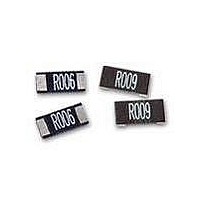
Current Sense Resistors - SMD 3W 0.001 OHM 1%
Manufacturer
IRC
Series
ULRr
Datasheet
1.ULR1R0015JLF.pdf
(6 pages)
Specifications of ULRG32512R001FLFSLT
Resistance
0.001 Ohms
Power Rating
3 Watts
Tolerance
1 %
Package / Case
2512 (6332 metric)
Product
Metal Element Current Sensing Resistors
Operating Temperature Range
- 55 C to + 170 C
Dimensions
3.2 mm W x 6.3 mm L x 0.6 mm H
Termination Style
SMD/SMT
Lead Free Status / RoHS Status
Lead free / RoHS Compliant


* Tolerance: The device manufacturer/supplier shall assure process compat-
ibility up to and including the stated classi cation temperature at the rated MSL
level.
Average Ramp-up rate (T smax to T p )
Preheat
- Temperature Min (T smin )
- Temperature Max (T smax )
- Time (T smin to T smax ) (ts)
Time maintained above
- Temperature (T L )
- Time (t L )
Peak Temperature (T P
Time within 5°C of actual Peak Temperature (tp) 2
R
Time 25°C to Peak Temperature
Wire and Film Technologies Division
Telephone: 361 992 7900 • Facsimile: 361 992 3377 • Website: www.irctt.com
1.6 mm - 2.5 mm
a
m
Thickness
Thickness
< 1.6 mm
≥ 2.5 mm
p
< 2.5 mm
≥ 2.5 mm
Package
Package
d -
o
w
n
Package Peak Re ow Temperatures
Package Peak Re ow Temperatures
R
Tabel 1: SnPb Eutectic Process -
a
e t
Pro le Feature
Tabel 2: Pb-free Process -
Volume mm 3
Volume mm 3 < 350
)
260°C *
260°C *
250°C *
< 350
240 +0/-5°C
225 +0/-5°C
* Based on Industry Standards and IPC recommendations
IRC Solder Re ow Recommendations
T
T
25
P
L
T
T
Volume mm 3
smax
smin
350 - 2000
260°C *
250°C *
245°C *
Volume mm 3 ≥ 350
• 4222 South Staples Street • Corpus Christi Texas 78411 USA
Sn-Pb Eutectic and Pb-Free Reflow Profiles
225 +0/-5°C
225 +0/-5°C
Preheat
3°C / second max.
° 6
t 25°C to Peak
Volume mm 3
Sn-Pb Eutectic
60 - 150 seconds
60 -120 seconds
t
10 - 30 seconds
s
6 minutes max.
C
260°C *
245°C *
245°C *
> 2000
Assembly
S
/
e
s
100°C
150°C
183°C
e
e
T
c
a
o
b
n
e l
d
m
1
a
. x
Time
Ramp-up
3°C / second max.
° 6
60 - 150 seconds
60 -180 seconds
20 - 40 seconds
8 minutes max.
C
Assembly
S
Note 1: Package volume excludes external
terminals (balls, bumps, lands, leads) and/or
non-integral heat sinks.
Note 2: The maximum component temperature
reached during re ow depends on package
thickness and volume. The use of convection
re ow processess reduces the thermal gradients
between packages. However, thermal gradients
due to differences in thermal mass of SMD pack-
ages may still exist.
Note 3: Components intended for use in “lead-
free” assembly process shall be evaluated using
the “lead-free” peak temperature and pro les
de ned in Table 1, 2 and re ow pro le whether
or not lead-free.
/
Pb-Free
e
s
150°C
200°C
217°C
e
e
T
c
a
t
t
o
P
L
b
n
e l
d
m
2
a
. x
Ramp-down
Critical Zone
T
Note 1: All temperatures refer
to topside of the package,
measured on the package
body surface.
Note 2: Time within 5 °C of
actual peak temperature (tp)
speci ed for the re ow pro les
is a “supplier” minimum and a
“user” maximum.
L
to T
ULR Issue April 2011 Sheet 5 of 6
P
Related parts for ULRG32512R001FLFSLT
Image
Part Number
Description
Manufacturer
Datasheet
Request
R

Part Number:
Description:
Day/night Infrared Led Camera ? Up To 164 Feet 50m
Manufacturer:
American Accurate Components
Datasheet:

Part Number:
Description:
Power MOSFET(Vdss=200V/ Rds(on)=0.40ohm/ Id=9.0A)
Manufacturer:
International Rectifier
Datasheet:
Part Number:
Description:
Miniatur-ir-temperatursensoren Abgesetzter Elektronik
Manufacturer:
ETC-unknow
Datasheet:
Part Number:
Description:
Infrarot-Temperatur-Messgerat
Manufacturer:
ASM-SENSOR [ASM GmbH]
Datasheet:
Part Number:
Description:
Miniatur-IR-Temperatursensoren mit abgesetzter Elektronik
Manufacturer:
ASM-SENSOR [ASM GmbH]
Datasheet:
Part Number:
Description:
IRC
Manufacturer:
International Resistive Company (IRC)
Part Number:
Description:
IRC
Manufacturer:
International Resistive Company (IRC)
Part Number:
Description:
IRC
Manufacturer:
International Resistive Company (IRC)
Part Number:
Description:
IRC
Manufacturer:
International Resistive Company (IRC)
Part Number:
Description:
IRC
Manufacturer:
International Resistive Company (IRC)
Part Number:
Description:
IRC
Manufacturer:
International Resistive Company (IRC)
Part Number:
Description:
IRC
Manufacturer:
International Resistive Company (IRC)
Part Number:
Description:
IRC
Manufacturer:
International Resistive Company (IRC)
Part Number:
Description:
IRC
Manufacturer:
International Resistive Company (IRC)
Part Number:
Description:
IRC
Manufacturer:
International Resistive Company (IRC)