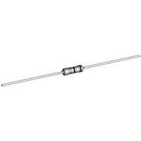
NFR25H0008208JA500 Vishay, NFR25H0008208JA500 Datasheet - Page 8

NFR25H0008208JA500
Manufacturer Part Number
NFR25H0008208JA500
Description
Metal Film Resistors - Through Hole 1/2watt 8.2ohm 5%
Manufacturer
Vishay
Series
NFRr
Type
Fusible Non-Flammable Resistorr
Datasheet
1.NFR2500004700JR500.pdf
(10 pages)
Specifications of NFR25H0008208JA500
Resistance
8.2 Ohms
Power Rating
0.5 Watt (1/2 Watt)
Temperature Coefficient
+/- 100 PPM / C
Tolerance
5 %
Voltage Rating
350 Volts
Termination Style
Axial
Operating Temperature Range
- 55 C to + 155 C
Dimensions
2.5 mm Dia. x 6.5 mm L
Resistance Tolerance
± 5%
Resistor Element Material
Metal Film
Resistor Case Style
Axial Leaded
No. Of Pins
2
Lead Free Status / RoHS Status
Lead free / RoHS Compliant
Lead Free Status / RoHS Status
Lead free / RoHS Compliant, Lead free / RoHS Compliant
Document Number: 28737
Revision: 30-Mar-10
TEST PROCEDURES AND REQUIREMENTS
IEC
60115-1
CLAUSE
4.4.1
4.4.2
4.5
4.18
4.29
4.17
4.7
4.16
4.16.2
4.16.3
4.16.4
4.20
4.22
4.19
4.23
4.23.2
4.23.3
4.23.4
4.23.5
4.23.6
4.24
4.25.1
4.25.3
4.8
4.12
4.26
4.6.1.1
METHOD
60068-2
21 (Ua1)
78 (Cab)
21 (Ub)
21 (Uc)
29 (Eb)
14 (Na)
30 (Db)
30 (Db)
20 (Tb)
45 (Xa)
20 (Ta)
13 (M)
TEST
2 (Ba)
1 (Aa)
6 (Fc)
IEC
(refer note on first page for
Damp heat (accelerated)
Damp heat (accelerated)
Temperature coefficient
Resistance to soldering
category temperature
Bending half number
Endurance (at 70 °C)
Insulation resistance
Dimensions (outline)
measuring distance)
Component solvent
Endurance at upper
Accidental overload
Climatic sequence:
Visual examination
Tensile all samples
Torsion other half
Low air pressure
remaining cycles
Rapid change of
Robustness of
Voltage proof
(steady state)
terminations:
on insulation
Solderability
Solderability
temperature
(after aging)
Resistance
Damp heat
of samples
of samples
resistance
For technical questions, contact:
Vibration
Dry heat
1
Bump
st
Noise
TEST
Cold
heat
cycle
Fusible, Non-Flammable Metal Film
Leaded Resistors
for 2 s at 235 °C: Solder bath (SnPb40)
displacement 1.5 mm or acceleration
3 x 1500 bumps in 3 directions; 40 g
Maximum voltage
10 g; 3 directions; total 6 h (3 x 2 h)
56 days; 40 °C; 90 % to 95 % RH;
Solder bath method; SnAg3Cu0.5
5 days; 55 °C; 95 % to 100 % RH
1000 h; loaded with
after 1 min; metal block method
Applied voltage (+ 0 %/- 10 %):
24 h; 55 °C; 90 % to 100 % RH
3 x 360° in opposite directions
Between - 55 °C and + 155 °C
Solder bath method; SnPb40
for 3 s at 245 °C: Solder bath
Thermal shock: 10 s; 260 °C;
Frequency 10 Hz to 500 Hz;
2 h; 8.5 kPa; 15 °C to 35 °C
8 h steam or 16 h, 155 °C;
Isopropyl alcohol or H
10 kΩ ≤
RMS
(IEC steps: 0 V to 100 V)
10 Ω ≤
30 min at UCT; 5 cycles
1.5 h ON and 0.5 h OFF
leads immersed 6 mm;
(SnAg3Cu0.5) method
100 Ω ≤
1 kΩ ≤
followed by brushing
loaded with 0.01
metal block method
30 min at LCT and
0.22 Ω ≤ R ≤ 4.7 Ω
Load 5 N; 4 x 90°
15 Ω < R ≤ 15 kΩ
4.7 Ω < R ≤ 15 Ω
3 mm from body
Load 10 N; 10 s
= 500 V during 1 min;
1000 h; no load
PROCEDURE
Cheese-cloth
16 h; 155 °C
filmresistorsleaded@vishay.com
Gauge (mm)
2 s; 235 °C:
3 s; 245 °C:
2 h; - 55 °C
< 10 Ω: 0.1 V
IEC 60195
< 100 Ω: 0.3 V
< 10 kΩ: 3 V
≤ 15 kΩ: 10 V
< 1 kΩ: 1 V
max.
70
DC = 500 V
or
70
2
O
max.
;
Vishay BCcomponents
≤ ± 200 ppm/K
≤ ± 200 ppm/K
≤ ± 100 ppm/K
No holes; clean surface; no damage
Δ max.: ± (0.25 %
Good tinning (≥ 95 % covered);
Good tinning (≥ 95 % covered);
Δ max.: ± (0.25 %
Δ max.: ± (0.25 %
Δ max.: ± (0.25 %
Δ max.: ± (0.25 %
Number of failures < 10 x 10
Number of failures < 10 x 10
Δ max.: ± (1.5 %
NFR25
Δ max.: ± (1 %
Δ max.: ± (1 %
Δ max.: ± (1 %
No breakdown or flashover
NFR25, NFR25H
See Dimensions Table
REQUIREMENTS
No visual damage
No visual damage
-
Non flammable
ins
ins
ins
No damage
No damage
No damage
nom.
no damage
no damage
< 0.1 μV/V
min.: 10
min.: 10
min.: 10
: max. ± 5 %
≤ ± 200 ppm/K
≤ ± 100 ppm/K
≤ ± 100 ppm/K
3
3
4
www.vishay.com
+ 0.05 Ω)
+ 0.05 Ω)
+ 0.05 Ω)
MΩ
MΩ
MΩ
NFR25H
+ 0.05 Ω)
+ 0.05 Ω)
+ 0.05 Ω)
+ 0.05 Ω)
+ 0.05 Ω)
+ 0.1 Ω)
-6
-6
8


