97-60-14P Amphenol, 97-60-14P Datasheet - Page 6
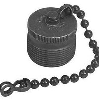
97-60-14P
Manufacturer Part Number
97-60-14P
Description
Circular MIL / Spec Connectors PLUG CAP 14 14S
Manufacturer
Amphenol
Series
97 Seriesr
Datasheet
1.97-79-513-8.pdf
(44 pages)
Specifications of 97-60-14P
Mil Type
MIL-DTL-5015
Product Type
Dustcaps
Shell Style
Plug
Mounting Style
Screw
Termination Style
Threaded
Shell Plating
Chromate over Cadmium, Olive Drab
Body Material
Metal
Lead Free Status / RoHS Status
Lead free / RoHS Compliant


97 series solder type
insert availability
8S-1
10SL-3
10SL-4
12SL-844 *
12S-3
12-5
12S-6 *
14S-1†
14S-2
14S-4 †
14S-5
14S-6
14S-7
14S-9†
16S-1
16S-4
16S-5
16S-6 †
16-7
16S-8
16-9
16-10
16-11 †
16-12
16-13
18-1
18-3†
18-4
18-5
18-8
18-9
18-10†
18-11
18-12†
18-13
18-16
18-19†
18-20
18-22†
18-29 †
18-420*
20-3†
Insert Number
Contacts
Total
10
10
1
3
2
4
2
1
2
3
4
1
5
6
3
2
7
2
3
3
3
5
4
3
2
1
2
2
4
3
8
7
4
5
6
4
1
5
3
5
1
3
1/16
1/16
1/16
1/16
1/16
1/8
1/16
1/16
1/8
1/16
1/16
1/16
1/8
1/16
1/16
1/16
1/16
1/16
1/16
1/16
1/16
1/16
1/16
1/8
1/8
1/8
1/16
1/16
1/16
1.16
1/16
5/16
1/16
1/16
1/8
1/16
1/8
Inches
Mechanical
Spacing
1.57
1.57
1.57
1.57
1.57
3.18
1.57
1.57
3.18
1.57
1.57
1.57
3.18
1.57
1.57
1.57
1.57
1.57
1.57
1.57
1.57
1.57
1.57
3.18
3.18
3.18
1.57
1.57
1.57
1.57
1.57
7.92
1.57
1.57
3.18
1.57
3.18
mm
Service
INST.
INST.
INST.
INST.
Rating
INST.
INST
A
A
A
A
D
A
D
A
A
A
D
A
A
A
A
A
A
A
A
A
A
D
D
D
A
A
A
A
A
C
A
A
D
A
D
0
1
4
Contact Size
1
1
8
Thermo-
Hi-Volt-
couple
age**
12
1
2
3
2
2
2
2
1
2
4
5
3
1
1
3
Thermo-
couple
10
16
1
3
2
4
2
2
3
4
1
5
6
3
2
7
2
3
3
2
5
2
4
6
4
1
7
5
6
5
3
5
4
Not all insert arrangements are currently available for environmental individual
wire seal. Consult Amphenol, Sidney, NY for availability.
† Inactive for new military design, but available for replacement or for non-mili-
* “MS” number not assigned. Use “97” prefix in place of “MS” in completing cata-
** Hi-Voltage = 17KVAC/24KVDC
20-4
20-6†
20-7
20-8
20-11†
20-14
20-15
20-16
20-17
20-18
20-19†
20-21
20-23
20-24
20-27
20-29
20-33
22-1†
22-2
22-4†
22-5
22-8†
22-9
22-10
22-11
22-12
22-13†
22-14
22-15
22-16†
22-18
22-19
22-20†
22-22
22-23
Insert Number
tary purposes.
log number. See how to order, page 19.
Molded-in pin (MIP) insert requires (910) deviation. See how to order, pg. 19.
Contacts
Total
13
14
17
11
19
14
4
3
8
6
5
7
9
6
9
3
9
2
4
2
3
4
6
2
3
4
2
5
5
6
9
8
9
4
8
1/8
1/8
1/8
1/16
1/16
1/16
1/16
1/16
1/16
1/16
1/16
1/16
1/16
1/16
1/16
1/16
1/8
1/8
1/16
1/8
3/16
3/16
3/16
1/4
1/8
1/8
1/16
1/16
3/16
1/16
1/16
1/8
1/16
1/16
1/16
1/16
1/8
1/16
Inches
Mechanical
Spacing
3.18
3.18
3.18
1.57
1.57
1.57
1.57
1.57
1.57
1.57
1.57
1.57
1.57
1.57
1.57
1.57
3.18
3.18
1.57
3.18
4.75
4.75
4.75
6.35
3.18
3.18
1.57
1.57
4.75
1.57
1.57
3.18
1.57
1.57
1.57
1.57
3.18
1.57
mm
Service
Rating
INST.
INST.
D
D
D
A
A
A
A
A
A
A
A
A
A
A
A
A
D
D
A
D
E
E
E
B
D
D
A
A
E
A
A
D
A
A
A
A
D
A
0
4
Contact Size
2
2
3
2
2
2
3
2
2
4
8
12
4
3
7
2
5
3
1
2
2
2
3
4
5
3
1
7
13
14
17
11
19
14
16
3
4
4
4
7
1
6
8
2
4
4
2
3
1
1
6
5
3
9
Related parts for 97-60-14P
Image
Part Number
Description
Manufacturer
Datasheet
Request
R

Part Number:
Description:
CONN CAP FOR SIZE 16 RECEPT
Manufacturer:
Amphenol Industrial Operations
Datasheet:

Part Number:
Description:
CONN CAP FOR SIZE 18 RECEPT
Manufacturer:
Amphenol Industrial Operations
Datasheet:

Part Number:
Description:
CONN CAP FOR SIZE 20 RECEPT
Manufacturer:
Amphenol Industrial Operations
Datasheet:

Part Number:
Description:
CONN CAP FOR SIZE 16 PLUG
Manufacturer:
Amphenol Industrial Operations
Datasheet:

Part Number:
Description:
CONN CAP FOR SIZE 28 RECEPT
Manufacturer:
Amphenol Industrial Operations
Datasheet:

Part Number:
Description:
Cable Specification: PU CABLE, UL20549 24AWG*8C+AD,OD= 6.0mm
Manufacturer:
Amphenol