09 03 096 3214 HARTING, 09 03 096 3214 Datasheet - Page 3
09 03 096 3214
Manufacturer Part Number
09 03 096 3214
Description
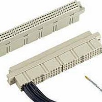
DIN 41612 Connectors 96P 2A FEMALE CBLMNT ORDER CONTACTS SEP.
Manufacturer
HARTING
Type
Cr
Specifications of 09 03 096 3214
Number Of Positions / Contacts
96
Termination Style
Crimp
Housing Material
Thermoplastic, Glass Filled
Contact Material
Copper Alloy
Number Of Rows
3
Pitch
2.54 mm
Pitch Spacing
2.54mm
No. Of Contacts
96
Gender
Receptacle
No. Of Rows
3
Rows Loaded
A + B + C
Mounting Type
PC Board Thru Hole
Connector Type
DIN 41612
Rohs Compliant
Yes
Body Style
Straight
Lead Free Status / RoHS Status
Lead free / RoHS Compliant


▲
b)
DIN 41 612 · Type B
Number of contacts
64, 32
Male connectors
Identification
Male connector
with angled
solder pins
Male connector
with straight
solder pins
Dimensions
Board drillings
Male connectors with 2 leading contacts [(0.8 mm) pos. a1 and
a32]. Lagging pins row b on request.
Other contact arrangements on request
Connectors with snap-in clips see chapter 00
Mounting side
SMC
SMC
of contacts arrangement
Number
62 + 2
62 + 2
64
32
32
64
64
32
32
64
▲
▲
Contact
Part No.
09 02 164 7921
09 02 132 7921
09 02 132 7931
09 02 164 7919
09 02 164 7922
09 02 132 7922
3
Performance levels according to IEC 60 603-2. Explanation chapter 00
c)
d)
f)
Railway classification NFF 16-101, Smoke index: F1,
Flammability class: I2
Connectors with coding see chapter 00
CTI > 400
d)
b)
b)
c)
c)
09 02 164 6921
09 02 164 6921 222
09 02 364 6921
09 02 664 6921
09 02 132 6921
09 02 632 6921
09 02 132 6931
09 02 332 6931
09 02 164 6951
09 02 164 6919
09 02 164 6922
09 02 132 6922
09 02 132 6932
09 02 164 6952
09 02 164 6920
Angled
solder pins
2
Cross area (A) of contacts row a, b:
b)
c)
c)
b)
d)
d)
f)
Straight
solder pins
Cross section of solder
A = 0.29 - 0.33 mm²
09 02 164 2921
09 02 132 2921
09 02 132 2931
09 02 164 2922
09 02 164 2952
Dimensions in mm
terminations
1
01 .
11
Related parts for 09 03 096 3214
Image
Part Number
Description
Manufacturer
Datasheet
Request
R

Part Number:
Description:
DIN 41612 Connectors SHELL HOUSING C FOR FEMALE TYPE C D
Manufacturer:
HARTING
Datasheet:


Part Number:
Description:
CONN HOUSING 6POS .156 W/O RAMP
Manufacturer:
Molex Inc
Datasheet:

Part Number:
Description:
CONN HOUSING 3POS .156 W/RAMP
Manufacturer:
Molex Inc
Datasheet:

Part Number:
Description:
CONN HOUSING 3POS .156 W/POLAR
Manufacturer:
Molex Inc
Datasheet:

Part Number:
Description:
CONN HOUSING 5POS .156 W/RAMP
Manufacturer:
Molex Inc
Datasheet:

Part Number:
Description:
CONN HOUSING 5POS .156 W/POLAR
Manufacturer:
Molex Inc
Datasheet:

Part Number:
Description:
CONN HOUSING 6POS .156 W/RAMP
Manufacturer:
Molex Inc
Datasheet:

Part Number:
Description:
CONN HOUSING 6POS .156 W/RAMP
Manufacturer:
Molex Inc
Datasheet:

Part Number:
Description:
CONN HOUSING 6POS .156 W/POLAR
Manufacturer:
Molex Inc
Datasheet:

Part Number:
Description:
CONN HOUSING 8POS .156 W/RAMP
Manufacturer:
Molex Inc
Datasheet:

Part Number:
Description:
CONN HOUSING 9POS .156 W/RAMP
Manufacturer:
Molex Inc
Datasheet: