Y92P-CXT4B Omron, Y92P-CXT4B Datasheet - Page 35
Y92P-CXT4B
Manufacturer Part Number
Y92P-CXT4B
Description
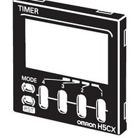
Mounting Hardware Front Panels - Rplc Black (N1.5)
Manufacturer
Omron
Type
Front Panel Replacementr
Datasheet
1.Y92P-CXT4B.pdf
(44 pages)
Specifications of Y92P-CXT4B
Color
Black
Features
Cover for Timer with 4 Digits
Product
Hardware
Lead Free Status / RoHS Status
Lead free / RoHS Compliant
For Use With
H5CX Series Timers


Connections
Block Diagram
Terminal Arrangement
(–)
Input Connections
The inputs of the H5CX-B are no-voltage (short-circuit or open) inputs or voltage inputs.
No-voltage Inputs (NPN Inputs)
Open Collector
No-voltage Input Signal Levels
Voltage Inputs (PNP Inputs)
No-contact Input (NPN Transistor)
Voltage Input Signal Levels
Note: 1. The DC voltage must be 30 VDC max.
0 V
No-contact
input
Contact input
High level (Input ON): 4.5 to 30 VDC
Low level (Input OFF): 0 to 2 VDC
6
1
PLC or
sensor
7
2
(+)
2. Input resistance: Approx. 4.7 kΩ
12
8
3
Sensor
OUT 2
Note: Operate with transistor ON
9
4
6
Input circuits
Short-circuit level (Transistor ON)
• Residual voltage: 3 V max.
• Impedance when ON: 1 kΩ max.
Open level (Transistor OFF)
• Impedance when OFF: 100 kΩ min.
Use contacts which can adequately switch 5 mA at 10 V
(Basic insulation)
10
13
5
(The leakage current is approx. 12 mA when the impedance is 0 Ω.)
Output circuit
7
Note: Operate with transistor OFF
6
OUT 1
8
7
9
Note: 1. The power supply and input circuit
8
Internal control
10
9
circuit
2. Terminals 1 and 6 are connected
3. Terminals 7 and 10 have the same
10
are not isolated.
internally.
reset function. The same function will
be performed whichever terminal is
connected. Terminals 7 and 10 are
not connected internally, however, so
do not use them for cross-over wiring.
Voltage Output
Sensor
Power supply
circuit
Display circuit
Key switch
Note: Operate with transistor ON
No-contact Input (PNP Transistor)
circuit
6
7
8
Sensor
9
10
Note: Operate with transistor ON
6
7
Contact Input
Input Circuits
Signal, Reset, and Gate Input
No-voltage Inputs (NPN Inputs)
IN
Transistor Output
8
• The transistor output of
• The diode connected to
the H5CX is insulated
from the internal circuitry
by a photocoupler, so the
transistor output can be
used as both NPN and
PNP output.
the collector of the output
transistor is used to
absorb inverted voltage
that is generated when an
inductive load is
connected to the H5CX.
Note: Operate with relay ON
9
6
10
7
1 kΩ
8
+14 V
9
Internal
circuit
Contact Input
10
• Leakage current:
• Switching capacity: 5 mA min.
• Residual voltage:
• Operating voltage: 10 VDC
NPN Output
DC Two-wire Sensor
Note: Operate with relay ON
Applicable Two-wire Sensor
Power for load
6
Voltage Inputs (PNP Inputs)
IN
Note: Operate with transistor ON
Approx. 4.7 kΩ
7
6
Timer
+
Load
Power for load
1.5 mA max.
3.0 VDC max.
8
7
H5CX-B@-N
9
+
8
PNP Output
10
9
Load
Inductive
load
Power for load
Internal
circuit
10
+
35
Related parts for Y92P-CXT4B
Image
Part Number
Description
Manufacturer
Datasheet
Request
R

Part Number:
Description:
Mounting Hardware Front Panels - Rplc White (5Y9.2 / 0.5)
Manufacturer:
Omron
Datasheet:
Part Number:
Description:
Mounting Hardware Front Panels - Rplc Light gray (5Y7/1)
Manufacturer:
Omron
Datasheet:

Part Number:
Description:
PNL CVR LITE GRAY
Manufacturer:
Omron
Datasheet:

Part Number:
Description:
PNL CVR BLACK
Manufacturer:
Omron
Datasheet:
Part Number:
Description:
PNL CVR MED GRAY
Manufacturer:
Omron
Datasheet:

Part Number:
Description:
G6S-2GLow Signal Relay
Manufacturer:
Omron Corporation
Datasheet:
Part Number:
Description:
Compact, Low-cost, SSR Switching 5 to 20 A
Manufacturer:
Omron Corporation
Datasheet:
Part Number:
Description:
Manufacturer:
Omron Corporation
Datasheet:
Part Number:
Description:
Manufacturer:
Omron Corporation
Datasheet:
Part Number:
Description:
Manufacturer:
Omron Corporation
Datasheet:
Part Number:
Description:
Manufacturer:
Omron Corporation
Datasheet: