Y92P-CXT4G Omron, Y92P-CXT4G Datasheet - Page 34
Y92P-CXT4G
Manufacturer Part Number
Y92P-CXT4G
Description
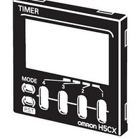
Mounting Hardware Front Panels - Rplc Light gray (5Y7/1)
Manufacturer
Omron
Type
Front Panel Replacementr
Datasheet
1.Y92P-CXT4B.pdf
(44 pages)
Specifications of Y92P-CXT4G
Color
Light Gray
Features
Cover for Timer with 4 Digits
Product
Hardware
Lead Free Status / RoHS Status
Lead free / RoHS Compliant
For Use With
H5CX Series Timers


34
H5CX-B@-N
Characteristics
Applicable Standards
I/O Functions
Response Delay Time When Resetting (Transistor Output)
The following table shows the delay from when the reset signal is input until the output is turned OFF.
Accuracy of operating time
and setting error
(including temperature and
voltage influences)
Insulation resistance
Dielectric strength
Impulse withstand voltage
Noise immunity
Static immunity
Vibration
resistance
Shock
resistance
Weight
Approved safety standards
EMC
Inputs
Outputs
Minimum reset signal width
Start signal
Reset
Gate
Forecast value
setting
Absolute value
setting
20 ms
1 ms
Destruction
Malfunction
Destruction
Malfunction
Control output (OUT2)
Forecast output (OUT1)
Control output 2 (OUT2)
Control output 1 (OUT1)
Power-ON start: ±0.01% ±50 ms max. (See note 1.)
Signal start: ±0.005%±0.03 ms max. (See note 1.)
Signal start for transistor output model: ±0.005%±3 ms max. (See note 1 and 2.)
If the set value is within the sensor waiting time at startup the control output of the H5CX will not turn ON until the sensor waiting
time passes.
Note: 1. The values are based on the set value.
100 MΩmin. (at 500 VDC) between current-carrying terminal and exposed non-current-carrying metal parts
2,000 VAC, 50/60 Hz for 1 min between current-carrying metal parts and non-current-carrying metal parts
1,000 VAC, 50/60 Hz for 1 min between control output, power supply, and input circuit
1.0 kV (between power terminals)
1.5 kV (between current-carrying terminal and exposed non-current-carrying metal parts)
±480 V (between power terminals) and ±600 V (between input terminals), square-wave noise by noise simulator
(pulse width: 100 ns/1 µs, 1-ns rise)
Destruction: 15 kV
Malfunction: 8 kV
10 to 55 Hz with 0.75-mm single amplitude in three directions for 2 h each
10 to 55 Hz with 0.35-mm single amplitude in three directions for 10 min each
300 m/s
100m/s
Approx. 105 g (Timer only)
UL508/Listing, CSA C22.2 No. 14, conforms to EN 61812-1 (pollution degree 2/overvoltage category III)
Conforms to VDE0106/P100 (finger protection).
(EMI)
Emission Enclosure:
(EMS)
Immunity ESD:
Immunity RF-interference:
Immunity Conducted Disturbance:
Immunity Burst:
Immunity Surge:
2. The value is applied for a minimum pulse width of 1 ms.
2
2
in three directions, three cycles
in three directions, three cycles
Output delay time
0.8 to 1.2 ms
15 to 25 ms
Starts timing.
• Resets present value. (The present value returns to 0.)
• Timing stops and control output turns OFF while reset input is ON.
• Reset indicator is lit while reset input is ON.
Inhibits timer operation.
Turns ON when the present value reaches the set value.
Turns ON when the present value reaches the forecast value.
Turns ON when the present value reaches set value 2.
Turns ON when the present value reaches set value 1.
(Reference value)
EN61812-1
EN55011 Group 1 class A
EN61812-1
EN61000-4-2: 6 kV contact discharge (level 2)
EN61000-4-3: 10 V/m (Amplitude-modulated, 80 MHz to 1 GHz) (level 3);
EN61000-4-6: 10 V (0.15 to 80 MHz) (level 3)
EN61000-4-4: 2 kV power-line (level 3);
EN61000-4-5: 1 kV line to lines (power and output lines) (level 3);
8 kV air discharge (level 3)
10 V/m (Pulse-modulated, 900 MHz 5 MHz) (level 3)
1 kV I/O signal-line (level 4)
2 kV line to ground (power and output lines) (level 3)
Related parts for Y92P-CXT4G
Image
Part Number
Description
Manufacturer
Datasheet
Request
R

Part Number:
Description:
Mounting Hardware Front Panels - Rplc Black (N1.5)
Manufacturer:
Omron
Datasheet:
Part Number:
Description:
Mounting Hardware Front Panels - Rplc White (5Y9.2 / 0.5)
Manufacturer:
Omron
Datasheet:

Part Number:
Description:
PNL CVR LITE GRAY
Manufacturer:
Omron
Datasheet:

Part Number:
Description:
PNL CVR BLACK
Manufacturer:
Omron
Datasheet:
Part Number:
Description:
PNL CVR MED GRAY
Manufacturer:
Omron
Datasheet:

Part Number:
Description:
G6S-2GLow Signal Relay
Manufacturer:
Omron Corporation
Datasheet:
Part Number:
Description:
Compact, Low-cost, SSR Switching 5 to 20 A
Manufacturer:
Omron Corporation
Datasheet:
Part Number:
Description:
Manufacturer:
Omron Corporation
Datasheet:
Part Number:
Description:
Manufacturer:
Omron Corporation
Datasheet:
Part Number:
Description:
Manufacturer:
Omron Corporation
Datasheet:
Part Number:
Description:
Manufacturer:
Omron Corporation
Datasheet: