LY2-0-DC 100 110 Omron, LY2-0-DC 100 110 Datasheet - Page 4
LY2-0-DC 100 110
Manufacturer Part Number
LY2-0-DC 100 110
Description
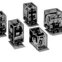
General Purpose / Industrial Relays 100VDC PWR Relay PC MNT DPDT
Manufacturer
Omron
Series
LYr
Datasheet
1.LY1-0-AC110120.pdf
(16 pages)
Specifications of LY2-0-DC 100 110
Contact Form
DPDT
Coil Voltage
100 VDC / 110 VDC
Contact Rating
10 A
Contact Termination
Solder Pin
Mounting Style
Through Hole
Power Consumption
0.9 W
Contact Material
Silver Alloy
Coil Current
9.1 mA / 10 mA
Coil Resistance
11 K Ohms
Coil Type
Non-Latching
Lead Free Status / RoHS Status
Lead free / RoHS Compliant
Other names
LY20100/110VDC LY20100110VDC


3-pole Type – AC
3-pole Type – DC
4-pole Type – AC
4-pole Type – DC
Note: 1. The rated current and coil resistance are measured at a coil temperature of 23°C (73°F) with tolerances of +15%, -20% for AC rated
288
6
12
24
50
100/110
120
200/220
240
6
12
24
48
100/110
6
12
24
50
100/110
120
200/220
240
6
12
24
48
100/110
voltage (V)
voltage (V)
voltage (V)
voltage
Rated
Rated
Rated
Rated
(V)
2. The AC coil resistance and inductance are reference values at 60 Hz.
3. The performance characteristics are measured at a coil temperature of 23°C (73°F).
4. Class B coil insulation is available.
current, and ±15% for DC rated coil resistance.
310
159
80
38
15.90/18.30 13.60/15.60 2,300
17.30
10.50/11.60 9.00/9.90
9.40
234
112
58.60
28.20
12.70/13
386
199
93.60
46.80
22.50/25.50 19/21.80
19.00
11.50/13.10 9.80/11.20
11.00
240
120
69
30
15/15.90
General Purpose Relay
Rated current (mA)
Rated current (mA)
Rated current (mA)
Rated current (mA)
50 Hz
50 Hz
270
134
67
33
14.8
8
330
170
80
40
16.40
9.50
60 Hz
60 Hz
6.70
24
100
410
2,450
8,650
10,400
25.70
107
410
1,700
8,500
5
20
78
350
1,800
2,200
6,700
9,000
25
100
350
1,600
6,900
resistance
resistance
resistance
resistance
Coil
Coil
Coil
Coil
(Ω)
(Ω)
(Ω)
(Ω)
LY
0.03
0.12
0.44
2.24
10.50
11.50
34.80
38.60
0.11
0.45
1.89
8.53
29.60
0.02
0.10
0.38
1.74
10.50
9.30
33.10
33.20
0.09
0.39
1.41
6.39
32
Armature
Armature
Armature
Armature
OFF
OFF
OFF
OFF
Coil inductance
Coil inductance
Coil inductance
Coil inductance
(ref. value) (H)
(ref. value) (H)
(ref. value) (H)
(ref. value) (H)
0.05
0.21
0.79
3.87
18.50
20.60
59.50
74.60
0.21
0.98
3.87
13.90
54.30
0.04
0.17
0.67
2.88
17.30
19
57.90
63.40
0.21
0.84
2.91
13.60
63.70
Armature
Armature
Armature
Armature
ON
ON
ON
ON
80% max.
80% max.
80% max.
80% max.
Pick-up
Pick-up
Pick-up
Pick-up
voltage
voltage
voltage
voltage
(% of rated voltage)
(% of rated voltage)
(% of rated voltage)
30% min.
10% min.
30% min.
10% min.
Dropout
Dropout
Dropout
Dropout
voltage
voltage
voltage
voltage
(% of rated voltage)
110%
110%
110%
110%
Maximum
Maximum
Maximum
Maximum
voltage
voltage
voltage
voltage
Approx.
1.60 to 2.00
(60 Hz)
Approx.
1.40
Approx.
1.95 to 2.50
(60 Hz)
Approx.
1.50
consumption
consumption
consumption
consumption
(VA, W)
(VA, W)
(VA, W)
(VA, W)
Power
Power
Power
Power