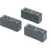
G6RL-1-SR-ASI DC24 Omron, G6RL-1-SR-ASI DC24 Datasheet - Page 2
G6RL-1-SR-ASI DC24
Manufacturer Part Number
G6RL-1-SR-ASI DC24
Description
General Purpose / Industrial Relays Shck Resist SPDT 24V AgSnIn, Sealed, 24V
Manufacturer
Omron
Series
G6RLr
Datasheet
1.G6RL-1A4-ASI-DC3.pdf
(8 pages)
Specifications of G6RL-1-SR-ASI DC24
Contact Form
SPDT
Coil Voltage
24 VDC
Contact Rating
12.6 mA
Contact Termination
Solder Pin
Mounting Style
Through Hole
Power Consumption
300 mW
Contact Material
Silver Tin Indium Alloy
Coil Current
9.2 mA
Coil Resistance
2618 Ohms
Lead Free Status / RoHS Status
Lead free / RoHS Compliant


Specifications
■ Coil Ratings
Note: 1. The above items are measured at a coil temperature of 23°C.
■ Contact Ratings
Note: 1. G6RL-1(A), G6RL-1(A)4-ASI: 8 A 250 VAC, resistive load; 5 A 24 VDC resistive load.
■ Characteristics
180
Rated voltage
Rated current
Coil resistance
Must operate voltage 70% max. of rated voltage
Must release voltage 10% min. of rated voltage
Max. voltage
Power consumption
Load
Rated load (See note 1.)
Rated carry current
Max. switching voltage
Max. switching current
Max. switching power
Failure rate (reference value) 10 mA at 5 VDC (P level) (See note 2.)
Contact resistance
Operate time
Release time
Insulation resistance
Dielectric strength
Impulse withstand voltage
Vibration resistance
Shock resistance
Endurance
Ambient temperature
Ambient humidity
Weight
Classification
2. The tolerance of the rated current is ±10%.
2. P level: λ 60 = 0.1 × 10
PCB Relay
3 VDC
73.3 mA
40 Ω
150% of rated voltage
Approx. 220 mW
G6RL
−6
Resistive load (cos φ = 1)
10 A at 250 VAC, NO resistive load
8 A at 250 VAC, resistive load
5 A at 30 VDC, resistive load
10 A at 250 VAC
5 A at 30 VDC
400 VAC, 300 VDC
NO: 10 A, NC: 8 A
NO: 2,500 VA, NC: 2,000 VA
150 W
100 mΩ max.
10 ms max. (SR Models: 15 ms max.)
5 ms max.
1,000 MΩ min. (at 500 VDC)
5,000 VAC, 50/60 Hz for 1 min between coil and contacts
1,000 VAC, 50/60 Hz for 1 min between contacts of same polarity
10 kV between coil and contacts (1.2 × 50 μs)
Destruction:
Malfunction:
Destruction: 1,000 m/s
Malfunction: NO: 200 m/s
SR Models: 250 m/s
Mechanical: 10,000,000 operations min. (at 18,000 operations/hr)
Operating: −40°C to 85°C (with no icing)
Operating: 5% to 85%
Approx. 7.8 g
/ operations
5 VDC
44 mA
113 Ω
6 VDC
36.7 mA
163 Ω
Standard, P1 load
10 to 55 to 10 Hz, 1.5-mm double amplitude
10 to 55 to 10 Hz, 0.825-mm single amplitude (1.65-mm double amplitude) when energized.
10 to 55 to 10 Hz, 0.4-mm single amplitude (0.8-mm double amplitude) when not energized.
2
(NO and NC) when not energized
2
12 VDC
18.3 mA
654 Ω
2
, NC: 50 m/s
24 VDC
9.2 mA
2,618 Ω
2
when not energized
48 VDC
5 mA
9,600 Ω
Approx.
240 mW
3 VDC
101 mA
30 Ω
80% max. of rated voltage
10% min. of rated voltage
150% of rated voltage (23°C)
Approx. 300 mW
5 VDC
60.2 mA
83 Ω
Shock resistance
6 VDC
50.1 mA
120 Ω
12 VDC
25.2 mA
476 Ω
24 VDC
12.6 mA
1,912 Ω