JW2ASN-DC24V Panasonic, JW2ASN-DC24V Datasheet - Page 5
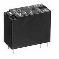
JW2ASN-DC24V
Manufacturer Part Number
JW2ASN-DC24V
Description
General Purpose / Industrial Relays 5A 24VDC DPST-NO NON-LATCHING PCB
Manufacturer
Panasonic
Datasheet
1.JW1FSN-DC5V.pdf
(7 pages)
Specifications of JW2ASN-DC24V
Contact Form
2 Form A
Coil Voltage
24 VDC
Contact Rating
5 A at 250 VAC, 5 A at 30 VDC
Coil Termination
Solder Pin
Contact Termination
Solder Pin
Mounting Style
Through Hole
Power Consumption
530 mW
Contact Material
Silver Tin Oxide
Coil Current
22 mA
Coil Resistance
1.1 K Ohms
Coil Type
Standard
Lead Free Status / RoHS Status
Lead free / RoHS Compliant
Available stocks
Company
Part Number
Manufacturer
Quantity
Price
Company:

Part Number:
JW2ASN-DC24V
Manufacturer:
PANASONIC
Quantity:
5 400


JW 2 Form C Standard (5 A) type
1. Maximum operating power
DIMENSIONS
JW 1 Form A
JW 1 Form C
CAD Data
CAD Data
10
1
0
AC resistive load (cos = 1.0)
10
Contact voltage, V
(mm inch)
100
1.128
28.6
1.126 .787
28.6 20
.138
.138
3.5
3.5
.138
3.5
All Rights Reserved © COPYRIGHT Panasonic Electric Works Co., Ltd.
1,000
16.5
.650
.094
.094
2.4
2.4
The CAD data of the products with a
.043
.299
12.8
.504
.043
12.8
.504
1.1
.299
7.6
1.1
7.6
2. Operate/release time
Sample: JW2SN-DC12V-F, 6 pcs.
Ambient temperature: 20 C
.031
.035
0.8
.787
0.9
External dimensions
External dimensions
20
.142
3.6
9
8
7
6
5
4
3
2
1
0
.012
80
0.3
Dimension:
Less than 1mm .039inch:
Min. 1mm
less than 3mm
Min. 3mm
Dimension:
Less than 1mm .039inch:
Min. 1mm
less than 3mm
Min. 3mm
.012
0.3
.016
0.4
90
.020
Coil applied voltage, %V
0.5
100
.039inch
.118
.039inch
.118
Release time
.012
0.3
Operate time
68 F
110
CAD Data
.118
inch:
.118
inch:
.012
0.3
.020
0.5
120
inch:
inch:
130
.016
0.4
mark can be downloaded from: http://panasonic-electric-works.net/ac
General tolerance
General tolerance
Max.
Max.
Min.
Max.
Min.
x -
x -
0.1
0.2
0.3
0.1
0.2
0.3
.142
.787
3.6
20
.020
0.5
.004
.008
.012
.004
.008
.012
Note: Terminal numbers are not indicated
Note: Terminal numbers are not indicated
PC board pattern (Bottom view)
PC board pattern (Bottom view)
4-1.3 dia.
4-.051 dia.
Wiring diagram (Bottom view)
Wiring diagram (Bottom view)
.094
2.4
.094
5-1.3 dia.
5-.051 dia.
2.4
on the relay.
on the relay.
.138 .138
3.5 3.5
N.O.
.138
3.5
1
1
Tolerance: 0.1
Tolerance: 0.1
4
4
2
16.5
.650
.787
6
20
6
Relay outline
N.O.
COM
N.C.
8
COM
8
Coil
Coil
Relay outline
.299
7.6
.299
7.6
JW
12.8
.504
.004
.004