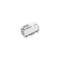
G6Z-1P-DC12 Omron, G6Z-1P-DC12 Datasheet - Page 3

G6Z-1P-DC12
Manufacturer Part Number
G6Z-1P-DC12
Description
Low Signal Relays - PCB NL 12VDC 75 Ohm Y terminal 2.6GHz
Manufacturer
Omron
Series
G6Zr
Specifications of G6Z-1P-DC12
Contact Form
1 Form C
Coil Voltage
12 VDC
Coil Current
16.7 mA
Coil Type
Non-Latching
Power Consumption
200 mW
Contact Carry Current
0.5 A
Termination Style
Solder Pin
Isolation
60 dB to 65 dB at 900 MHz / 30 dB to 45 dB at 2.6 GHz
Insertion Loss
0.1 dB to 0.2 dB at 900 MHz / 0.3 dB to 0.5 dB at 2.6 GHz
Maximum Switching Current
0.5 A
Contact Rating
30 V
Coil Frequency Max
2.6GHz
Coil Voltage Vdc Nom
12V
Contact Current Max
500mA
Contact Voltage Ac Nom
30V
Contact Voltage Dc Nom
30V
Coil Resistance
720.4ohm
Contact Configuration
SPDT
Lead Free Status / RoHS Status
Lead free / RoHS Compliant
Lead Free Status / RoHS Status
Lead free / RoHS Compliant, Lead free / RoHS Compliant
Other names
G6Z-1P-12DC, G6Z1P12DC
G6Z
Specifications
I
Note:
I
Note:
120
Load
Rated load
Rated carry current
Max. switching voltage
Max. switching current
Item
Isolation
Insertion loss (not in-
cluding substrate loss)
V.SWR
Return loss
Maximum carry power
Maximum switching power
Contact Ratings
High-frequency Characteristics
This value is for an impedance of 50 Ω or 75 Ω with a V.SWR of 1.2 max.
1. The above values are initial values.
2. These values are for an impedance of 50 Ω or 75 Ω with a V.SWR of 1.2 max.
Frequency
75 Ω
50 Ω
75 Ω
50 Ω
75 Ω
50 Ω
75 Ω
50 Ω
65 dB min.
60 dB min.
0.2 dB max.
0.1 dB max.
1.2 max.
1.1 max.
20.8 dB min.
26.4 dB min.
10 W (See note 2.)
10 W (See note 2.)
E-shape
Resistive load
10 mA at 30 VAC; 10 mA at 30 VDC; 10 W at 900 MHz (See note.)
0.5 A
30 VAC, 30 VDC
0.5 A
TH
Y-shape
900 MHz
60 dB min.
E-shape
SMD
Y-shape
35 dB min. 45 dB min. 30 dB min. 40 dB min.
0.5 dB max.
0.3 dB max.
1.5 max.
1.3 max.
14.0 dB min.
17.7 dB min.
E-shape
TH
Y-shape
2.6 GHz
E-shape
SMD
Y-shape
G6Z


