G6S-2F-Y DC5 Omron, G6S-2F-Y DC5 Datasheet - Page 3
G6S-2F-Y DC5
Manufacturer Part Number
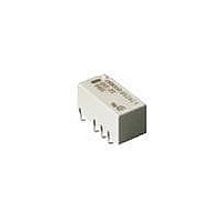
G6S-2F-Y DC5
Description
Low Signal Relays - PCB EN60950 SMT Relay
Manufacturer
Omron
Series
G6Sr
Datasheet
1.G6S-2F-Y_DC5.pdf
(12 pages)
Specifications of G6S-2F-Y DC5
Contact Form
2 Form C (DPDT)
Coil Voltage
5 V
Coil Current
28.1 mA
Power Consumption
140 mW
Contact Carry Current
2 A
Termination Style
Solder Tail
Maximum Switching Current
2 A
Contact Rating
2 A
Lead Free Status / RoHS Status
Lead free / RoHS Compliant
Other names
BY DC5 G6S2FY G6S2FYDC5BYOMR OMR


G6S
Single-side Stable EN60950/EN41003 Approved Type (G6S-2-Y, G6S-2F-Y, G6S-2G-Y)
Note:
■
Note:
■
Note:
Note:
Rated voltage
Rated current
Coil resistance
Must operate voltage
Must release voltage
Max. voltage
Power consumption
Load
Rated load
Contact material
Rated carry current
Max. switching voltage
Max. switching current
Max. switching power
Failure rate (reference value)
(See note.)
Contact resistance (See note 1.)
Operate (set) time (See note 2.)
Release (reset) time (See note 2.)
Bounce time
Max. operating frequency
Insulation resistance (See note 3.)
Dielectric strength
Impulse withstand voltage
Vibration resistance
Shock resistance
Endurance
Ambient temperature
Ambient humidity
Weight
Contact Ratings
Characteristics
1. The rated current and coil resistance are measured at a coil temperature of 23°C with a tolerance of ±10%.
2. Operating characteristics are measured at a coil temperature of 23°C.
3. The maximum voltage is the highest voltage that can be imposed on the relay coil.
P level:
This value was measured at a switching frequency of 120 operations/min and the criterion of contact resistance is 50 Ω. This value
may vary depending on the operating environment. Always double-check relay suitability under actual operating conditions.
The above values are initial values.
1. The contact resistance was measured with 10 mA at 1 VDC with a voltage drop method.
2. Values in parentheses are actual values.
3. The insulation resistance was measured with a 500-VDC megohmmeter applied to the same parts as those used for checking
the dielectric strength (except between the set and reset coil).
λ
60
= 0.1 x 10
-6
/operation
5 VDC
40 mA
125 Ω
75% max. of rated voltage
10% min. of rated voltage
170% of rated voltage at 23°C
Approx. 200 mW
Resistive load (cosφ = 1)
0.5 A at 125 VAC; 2 A at 30 VDC
Ag (Au-Alloy)
2 A
250 VAC, 220 VDC
2 A
62.5 VA, 60 W
10 µA at 10 mVDC
75 mΩ max.
4 ms max. (approx. 2.5 ms; latching type: approx. 2 ms)
4 ms max. (approx. 1.5 ms; latching type: approx. 2 ms)
Operate: Approx. 0.5 ms
Release: Approx. 0.5 ms
Set/Reset: Approx. 0.5 ms
Mechanical: 36,000 operations/hr
Electrical: 1,800 operations/hr (under rated load)
1,000 MΩ min. (at 500 VDC)
2,000 VAC, 50/60 Hz for 1 min between coil and contacts
1,000 VAC, 50/60 Hz for 1 min between coil and contacts (double-winding latching)
1,500 VAC, 50/60 Hz for 1 min between contacts of different polarity
1,000 VAC, 50/60 Hz for 1 min between contacts of same polarity
500 VAC, 50/60 Hz for 1 min between set and reset coil (double-winding latching)
2,500 V (2 x 10 µs) between coil and contacts
1,500 V (10 x 160 µs) between coil and contacts (double-winding latching)
2,500 V (2 x 10 µs) between contacts of different polarity
1,500 V (10 x 160 µs) between contacts of same polarity (conforms to FCC Part 68)
Destruction: 10 to 55 to 10 Hz, 2.5-mm single amplitude (5-mm double amplitude)
Malfunction: 10 to 55 to 10 Hz, 1.65-mm single amplitude (3.3-mm double amplitude)
Destruction: 1,000 m/s
Malfunction: 750 m/s
Mechanical: 100,000,000 operations min. (at 36,000 operations/hr)
Electrical: 100,000 operations min. (2 A at 30 VDC, resistive load: 1,200 operations/hr)
100,000 operations min. (0.5 A at 125 VAC, resistive load)
Operating: −40°C to 85°C (with no icing), −40°C to 70°C (double-winding latching, 24 VDC)
Operating: 5% to 85%
Approx. 2 g
2
(approx. 75G)
2
(approx. 100G)
12 VDC
16.7 mA
720 Ω
24 VDC
9.6 mA
2,504 Ω
170% of rated voltage
at 23°C
Approx. 230 mW
G6S
3
Related parts for G6S-2F-Y DC5
Image
Part Number
Description
Manufacturer
Datasheet
Request
R

Part Number:
Description:
EN60950 SMT Relay Tape & Reel
Manufacturer:
Omron
Datasheet:
Part Number:
Description:
EN60950 SMT Relay
Manufacturer:
Omron
Datasheet:
Part Number:
Description:
EN60950 SMT Relay Tape & Reel
Manufacturer:
Omron
Datasheet:
Part Number:
Description:
EN60950 SMT Relay
Manufacturer:
Omron
Datasheet:
Part Number:
Description:
EN60950 SMT Relay
Manufacturer:
Omron
Datasheet:
Part Number:
Description:
EN60950 SMT Relay Tape & Reel
Manufacturer:
Omron
Datasheet:
Part Number:
Description:
EN60950 SMT Relay Tape & Reel
Manufacturer:
Omron
Datasheet:
Part Number:
Description:
EN60950 SMT Relay Tape & Reel
Manufacturer:
Omron
Datasheet:
Part Number:
Description:
EN60950 SMT Relay Tape & Reel
Manufacturer:
Omron
Datasheet:
Part Number:
Description:
EN60950 SMT Relay Tape & Reel
Manufacturer:
Omron
Datasheet:
Part Number:
Description:
EN60950 SMT Relay
Manufacturer:
Omron
Datasheet:
Part Number:
Description:
EN60950 SMT Relay
Manufacturer:
Omron
Datasheet:
Part Number:
Description:
EN60950 SMT Relay
Manufacturer:
Omron
Datasheet:

Part Number:
Description:
Low Signal Relays - PCB EN60950 SMT Relay
Manufacturer:
Omron
Datasheet:
Part Number:
Description:
EN60950 SMT RELAY
Manufacturer:
Omron
Datasheet: