G5V-2-H1-DC12 Omron, G5V-2-H1-DC12 Datasheet - Page 4
G5V-2-H1-DC12
Manufacturer Part Number
G5V-2-H1-DC12
Description
Low Signal Relays - PCB DPDT PCB 12VDC
Manufacturer
Omron
Series
G5Vr
Datasheet
1.G5V-2-DC12.pdf
(6 pages)
Specifications of G5V-2-H1-DC12
Contact Form
DPDT
Coil Voltage
12 VDC
Coil Current
30 mA
Coil Type
High Sensitivity
Power Consumption
150 mW
Termination Style
PCB Terminals
Maximum Switching Current
2 A
Contact Rating
0.50 A at 125 VAC, 2 A at 30 VDC
Current, Rating
0.5⁄1 AAC⁄ADC
Diameter, Mounting
0.039 in. Dia. (Hole)
Dielectric Rating
1000 VAC @ 50⁄60 Hz for 1 minute between coil and contacts
Dimensions
0.807 in. L x 0.398 in. W x 0.453 in. H
Function
Sensitive
Material, Contact
Ag (Au clad)
Number Of Pins
8
Power, Rating
62.5⁄24 VA⁄W
Relay Type
Electro Mechanical
Standards
UL, CSA, FCC, RoHS
Temperature, Operating, Maximum
70 °C
Temperature, Operating, Minimum
-25 °C
Voltage, Control
12 VDC
Voltage, Rating
125 VAC
Lead Free Status / RoHS Status
Lead free / RoHS Compliant
Other names
G5V2H112DC OMRG5V2H112DC
Available stocks
Company
Part Number
Manufacturer
Quantity
Price

Part Number:
G5V-2-H1-DC12
Manufacturer:
OMRON/欧姆龙
Quantity:
20 000
Company:
Part Number:
G5V-2-H1-DC12V
Manufacturer:
OMRON
Quantity:
12 000
Company:
Part Number:
G5V-2-H1-DC12V
Manufacturer:
OMRON
Quantity:
20 000


Dimensions
Note: 1. All units are in millimeters unless otherwise indicated.
G5V-2, G5V-2-H1
■ Approvals
UL Recognized (File No. E41515) / CSA Certified (File No. LR31928) - - Ambient Temp. = 40°C
Note: 1. The rated values approved by each of the safety standards may be different from the performance characteristics individually defined in this catalog.
Precautions
Long-term Continuously ON Contacts
Using the Relay in a circuit where the Relay will be ON continuously
for long periods (without switching) can lead to unstable contacts
because the heat generated by the coil itself will affect the insulation,
causing a film to develop on the contact surfaces. Be sure to use a
fail-safe circuit design that provides protection against contact failure
or coil burnout.
80
G5V-2
G5V-2-H1
2. Tolerance: ±0.1
3. Orientation marks are indicated as follows:
2. In the interest of product improvement, specifications are subject to change.
Type
Low Signal Relay
DPDT
0.5
20.5 max.
20.3 typ.
Contact form
G5V-2
0.3
3 to 48 VDC
3 to 48 VDC
10.1 max.
9.9 typ.
7.62
Coil rating
3.5
0.5
11.5 max.
11.4 typ.
Terminal Arrangement/
Internal Connections
(Bottom View)
Relay Handling
When washing the product after soldering the Relay to a PCB, use a
water-based solvent or alcohol-based solvent, and keep the solvent
temperature to less than 40°C. Do not put the Relay in a cold clean-
ing bath immediately after soldering.
16
1
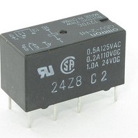
0.6 A at 125 VAC (General Use)
0.6 A at 110 VDC (Resistive)
2 A at 30 VDC (Resistive)
0.5 A at 125 VAC (General Use)
0.2 A at 110 VDC (Resistive)
1 A at 24 VDC (Resistive)
13
4
11
6
9
8
(1.3)
Eight, 1-dia. holes
Contact ratings
7.62
Tolerance: ±0.1
Mounting Holes
(Bottom View)
5.08 5.08
7.62
(1.3)
(1.2)
Related parts for G5V-2-H1-DC12
Image
Part Number
Description
Manufacturer
Datasheet
Request
R

Part Number:
Description:
RELAY DPDT 1A 48VDC PCB
Manufacturer:
Omron
Datasheet:

Part Number:
Description:
RELAY PCB DPDT HI-SENSE 24VDC
Manufacturer:
Omron
Datasheet:

Part Number:
Description:
LOW SIGNAL RELAY
Manufacturer:
Omron
Datasheet:
Part Number:
Description:
RELAY PCB DPDT HI-SENSE 5VDC
Manufacturer:
Omron
Datasheet:
Part Number:
Description:
RELAY PCB DPDT HI-SENSE 12VDC
Manufacturer:
Omron
Datasheet:

Part Number:
Description:
LOW SIGNAL RELAY
Manufacturer:
Omron
Datasheet:
Part Number:
Description:
LOW SIGNAL RELAY
Manufacturer:
Omron
Datasheet:

Part Number:
Description:
Low Signal Relays - PCB DPDT PCB 24VDC
Manufacturer:
Omron
Datasheet:

Part Number:
Description:
LOW SIGNAL RELAY
Manufacturer:
Omron
Datasheet:

Part Number:
Description:
SIGNAL RELAY, DPDT, 48VDC, 1A, THD
Manufacturer:
Omron
Datasheet:

Part Number:
Description:
LOW SIGNAL RELAY
Manufacturer:
Omron
Datasheet:

Part Number:
Description:
Manufacturer:
Omron Corporation
Datasheet:
Part Number:
Description:
Manufacturer:
Omron Corporation
Datasheet: