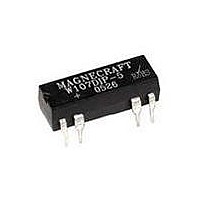
W171DIP-28 Magnecraft / Schneider Electric, W171DIP-28 Datasheet - Page 8

W171DIP-28
Manufacturer Part Number
W171DIP-28
Description
Reed Relay DPST-NO W/DIODE 24V
Manufacturer
Magnecraft / Schneider Electric
Type
DIP Reed Relaysr
Specifications of W171DIP-28
Contact Form
DPST - NO
Coil Voltage
24 V
Maximum Switched Current
0.5 A
Coil Suppression Diode
Yes
Coil Resistance
2200 Ohms
Termination Style
Solder
Current, Rating
0.5 A
Dielectric Strength
500 V (RMS) (Coil to Contacts), 150 V (RMS) (Across Open Contacts)
Function
Power
Material, Contact
Rhodium
Mounting Type
PCB
Number Of Pins
8
Relay Type
Reed
Resistance, Coil
2200 Ohms (Nom.)
Standards
RoHS
Temperature, Operating
-40 to +85 °C
Termination
Solder
Voltage, Control
24 VDC
Voltage, Rating
100 VDC
Weight
1 g
Coil Voltage Vdc Nom
24V
Switching Current Max
500mA
Switching Voltage Max
100VDC
Contact Configuration
DPST-NO
Relay Mounting
PCB
External Height
7.62mm
Rohs Compliant
Yes
Lead Free Status / RoHS Status
Lead free / RoHS Compliant
Other names
171DIP-28
6...
GENERAL
COIL
CONTACTS
TIMING
DIELECTRIC STRENGTH
TEMPERATURE
SHOCK RESISTANCE
VIBRATION RESISTANCE
LIFE EXPECTANCY
MISCELLANEOUS
GENERAL
CLASS
Across Open Contacts:
Pull-in Voltage:
Drop Out Voltage:
Max. Voltage:
Resistance:
Coil Power:
Duty:
Contact Material:
Contact Resistance:
Contact Rating:
Operate time:
Release time:
Between Mutually
Insulation Resistance:
Capacitance:
Operating:
Storage:
Operating:
Operating:
Electrical:
Mechanical:
Operating Position:
Enclosure:
Weight:
7
Insulation Points:
117SIP
PHONE: (843) 393-5778 FAX: (843) 393-4123 EMAIL: info@magnecraft.com
SPECIFICA
SPECIFICA
85% of nominal voltage or less
10% of nominal voltage or more
110% of nominal voltage
±10% measured @ 25˚C
See chart
Continuous
Rhodium
200 milliohms max
0.5 amp 200 VDC (10VA)
1.2 amps max. Continuous carry current
1 mS or less @ nominal voltage
1 mS or less @ nominal voltage
150 V rms
500 V rms
1000 megohms min. @ 500 VDC
1.0 pf typical coil to contact
-40˚C to +85˚C @ rated operation
-40˚C to +105˚C
50 g's
20 g's, 40 Hz to 200 Hz
50,000,000 operations
@ 5-10 V @ 10 mA
100,000,000 operations @ no load
Any
Epoxy molded
1 gram approx.
WHEN SPACING SIP RELAYS, THE RELAYS
REQUIRE 1/2 INCH SPACING FROM THE SIDE
OF THE ADJACENT RELAYS.
TIONS
TIONS
SINGLE IN - LINE PACKAGE REED RELAY
SPST - N. O.
SPST - N. C.
SPST - N. O. WITH CLAMPING DIODE
0.290 MAX.
SPST - N. C. WITH CLAMPING DIODE
1
1
1
1
DIAGRAMS
0.075 TYP.
0.020 TYP.
(7.36)
(TOP VIEWED )
WIRING
(1.90)
(0.51)
3+
3+
3
3
DIMENSIONS SHOWN IN INCHES & (MILLIMETERS).
5
5-
5-
5
OUTLINE DIMENSIONS
7
7
7
7
PIN NO.1
INDICATOR
0.750 MAX.
0.600 TYP.
0.200 TYP.
(5.08)
STANDARD
(19.0)
(15.2)
NUMBERS
W117SIP-1
W117SIP-3
W117SIP-5
W117SIP-22
W117SIP-23
W117SIP-24
W117SIP-6
W117SIP-8
W117SIP-10
W117SIP-18
W117SIP-25
W117SIP-26
SPST-N.O. OR N.C., 0.5 AMP
PART
SEE END OF SECTION 6 FOR CROSS REFERENCE
VOLTAGE
NOMINAL
INPUT
0.260 MAX
COIL MEASURED @ 25˚C
0.290 MAX.
12
24
12
24
12
24
12
24
(6.60)
5
5
5
5
(7.36)
0.140TYP.
(3.55)
0.030 TYP.
(0.762)
RESISTANCE
NOMINAL
(OHMS)
1000 Ω
2000 Ω
1200 Ω
2200 Ω
1000 Ω
2000 Ω
1200 Ω
2200 Ω
500 Ω
500 Ω
500 Ω
500 Ω
0.010 TYP.
(0.25)
(2.79)
0.110
NOMINAL
POWER
(mW)
144
288
120
270
144
288
120
220
50
50
50
50


