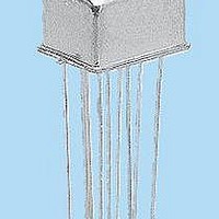
J116C-5M TELEDYNE, J116C-5M Datasheet - Page 2

J116C-5M
Manufacturer Part Number
J116C-5M
Description
RF (Radio Frequency) Relays DPDT 5VDC 0.1ohm
Manufacturer
TELEDYNE
Series
116Cr
Datasheet
1.J116C-5M.pdf
(6 pages)
Specifications of J116C-5M
Contact Form
2 Form C (DPDT)
Coil Voltage
5 VDC
Termination Style
PCB
Lead Free Status / RoHS Status
Lead free / RoHS Compliant
116C Page 2
SERIES 116C
GENERAL ELECTRICAL SPECIFICATIONS (–65°C to +125°C unless otherwise noted) (Notes 2 & 3)
DETAILED ELECTRICAL SPECIFICATIONS (–65°C to +125°C unless otherwise noted) (Note 3)
PERFORMANCE CURVES
(NOTE 2)
Contact Arrangement
Rated Duty
Contact Resistance
Contact Load Ratings (DC)
(See Fig. 2 for other DC
resistive voltage/current ratings)
Contact Load Ratings (AC)
Contact Life Ratings
Contact Overload Rating
Contact Carry Rating
Operate Time
Release Time
Contact Bounce
Intercontact Capacitance
Insulation Resistance
Dielectric Strength
Negative Coil Transient (Vdc)
Diode P.I.V. (Vdc)
Zener Voltage (Vdc)
Zener Leakage Current (AμA @ 15.2 Vdc)
Coil Voltage (Vdc)
Coil Current (mAdc @25°C)
Nominal Coil Operating Power @ 25°C (Milliwatts)
Pick-up Voltage (Vdc) (Note 4)
Drop-out Voltage (Vdc)
(Note 4)
–65°C to +125°C
Characteristics
10
20
30
40
50
60
70
.1
.2
.3
.4
Power FET
0
.01
TYPICAL RF PERFORMANCE
0.5
FREQUENCY (GHz)
(See Note 8 for full P/N example)
FIGURE 1
Gate Voltage to Turn Off (Vdc, Max.)
Gate Voltage to Turn On (Vdc, Max.)
Drain-Source Voltage (Vdc, Max.)
.1
SPECIFICATIONS ARE SUBJECT TO CHANGE WITHOUT NOTICE
2 Form C (DPDT)
Continuous
0.1 ohm max. before life; 0.2 ohm max. after life at 1A/28Vdc (measured 1/8" from header)
Resistive:
Inductive:
Lamp:
Low Level:
Resistive:
2A/28Vdc Resistive (100 cycles min.)
Contact factory
2.5 msec max. at nominal rated coil voltage
4.0 msec max.
1.5 msec max.
0.4 pf typical
10,000 megohms min. between mutually isolated terminals
Atmospheric pressure: 500 Vrms/60Hz
10,000,000 cycles (typical) at low level
1,000,000 cycles (typical) at 0.5A/28Vdc resistive
100,000 cycles min. at all other loads specified above
BASE PART
.5
NUMBERS
1.0
Nom.
Max.
Max.
Max.
Max.
Min.
Min.
1.92
1.22
1.07
1.02
1.01
1.00
1.00
1 Amp/28Vdc
200 mA/28Vdc (320 mH)
100 mA/28Vdc
10 to 50 μA/10 to 50mV
250 mA/115Vac, 60 and 400 Hz (Case not grounded)
100 mA/115Vac, 60 and 400 Hz (Case grounded)
www.teledynerelays.com
116C-5
132.3
96.5
0.13
641
5.0
5.6
4.0
2.3
300
250
200
150
100
50
0
0.1
116C-6
83.9
60.3
0.18
462
6.0
8.0
4.9
3.2
0.2
TYPICAL DC CONTACT RATING (RESISTIVE)
0.3
116C-9
12.0
47.1
33.1
0.27
368
9.0
7.3
4.9
LOAD CURRENT (AMPS DC)
0.4
70,000 ft.: 125 Vrms/60Hz
FIGURE 2
0.5
116C-12
12.0
16.0
36.1
24.9
0.36
369
9.8
6.5
17 min. to 23 max.
0.6
3.8 (Note 4)
©2003 TELEDYNE RELAYS
100 min.
1.0 max
2.5 max
0.7
0.5
55
116C-18
18.0
24.0
24.1
16.1
14.6
0.54
368
9.8
0.8
0.9
116C/1203/Q1
116C-26
26.5
32.0
19.9
12.9
19.5
0.72
13.0
450
1.0


