J114DDM4-26M TELEDYNE, J114DDM4-26M Datasheet
J114DDM4-26M
Specifications of J114DDM4-26M


Related parts for J114DDM4-26M


J114DDM4-26M Summary of contents
Page 1
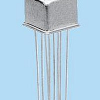
... PC board spacing are required. The basic design and internal construction are similar to the standard Teledyne DPDT TO-5 relay (e.g., Series 412). The following unique construction features and manufacturing techniques provide overall high reliability and excellent resistance to environmental extremes: • ...
Page 2
... TYPICAL DC CONTACT RATING (RESISTIVE) 0.1 0.2 0.3 0.4 0.5 0.6 0.7 LOAD CURRENT (AMPS DC) FIGURE 2 ©2006 TELEDYNE RELAYS 114-26 114D-26 114DD-26 26.5 32.0 1560 1560 14.8 18.5 18.0 19.0 0.89 13.0 1.4 13.0 0.8 ...
Page 3
... DIMENSIONS ARE SHOWN IN INCHES (MILLIMETERS) 2 ® Teledyne Part Numbering System for 114 Teledyne Part Numbering System for Military Qualified (JAN) Relays J 114 www.teledynerelays.com SCHEMATIC DIAGRAMS .035 ±.010 (.89 ±.25) .100 ±.010 114 (2.54 ±.25) TYP 8 PLACES 114D 114DD SCHEMATICS ARE VIEWED ...
Page 4
... Dimensions are in inches (mm). 4. Unless otherwise speci¿ ed, tolerance is ± .010 (.25). 5. Add the contact resistance show in the datasheet. 6. Add 0.01 oz. (0. the weight of the relay assembly shown in the datasheet. © 2008 Teledyne Relays Appendix A: Spacer Pads Height For use with the following: ...
Page 5
... Dim H MAX .014 [0.36] (REF) .370 [9.4] MIN +44 (0) 1236 453124 • www.teledyne-europe.com For use with the following: ER411T, J411T, ER412, ER412D ER412DD, J412, J412D, J412DD ER412T, J412T 712, 712D, 712TN ER431T, J431T, ER432, ER432D ER432DD, J432, J432D, J432DD ER432T, J432T ...
Page 6
... Centigrid® Relays: RF180, ER116C, 122C, ER136C Indicates ground pin position Indicates glass insulated lead position Indicates ground pin or lead position depending on relay type © 2008 Teledyne Relays "Z" POSITION "X" POSITION "Y" POSITION TO-5 Relays: ER411, ER431, RF311, RF331 " ...