RF300-12 TELEDYNE, RF300-12 Datasheet - Page 5
RF300-12
Manufacturer Part Number
RF300-12
Description
RF (Radio Frequency) Relays 12V DC-6GHz .15W
Manufacturer
TELEDYNE
Series
RF300/303r
Specifications of RF300-12
Coil Resistance
390 Ohms
Frequency
3 GHz
Contact Form
DPDT
Coil Voltage
12 VDC
Power Consumption
450 mW
Termination Style
PCB
Coil Voltage Vdc Nom
12V
Contact Current Max
1A
Contact Voltage Dc Nom
28V
Coil Type
DC Coil
Relay Mounting
PC Board
External Width
9.4mm
Contact Configuration
DPDT
Contact
RoHS Compliant
Brand/series
RF300 Series
Capacitance
0.4 pF (Typ.)
Current, Rating
1 A
Diameter, Body
0.370 in. (Max.)
Diameter, Lead
0.017 in.
Function
Frequency (RF)
Height
0.275 in. (Max.)
Length, Lead
0.75 in.
Mounting Type
PCB
Number Of Pins
10
Package Type
TO-5
Relay Type
Electro Mechanical
Resistance, Coil
390 Ohms +⁄- 20%
Resistance, Contact
0.15 Ohms (Max.)
Temperature, Operating
-55 to +85 °C
Termination
Leadwires
Voltage, Control
12 VDC
Voltage, Rating
28 VDC
External Height
6.99mm
Rohs Compliant
Yes
Lead Free Status / RoHS Status
Lead free / RoHS Compliant
Lead Free Status / RoHS Status
Lead free / RoHS Compliant


© 2010 TELEDYNE RELAYS
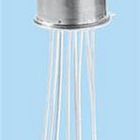
SERIES RF300/RF303
OUTLINE DIMENSIONS
GENERAL NOTES
I.
II. For reference only. Coil resistance not directly measureable at relay terminals due to internal series diode.
SCHEMATIC DIAGRAMS
General Note: Parts ordered without suffi x may be supplied with Solder-Coated or Gold-Plated leads
1
2
NOTES:
1. DIMENSIONS ARE IN INCHES, METRIC EQUIVALENTS SHOWN IN [ ].
2. POSTITIONS 5 AND 10 ARE FOR UNINSULATED CASE GROUND OPTIONS.
3. NO PROTRUSION BELOW BOTTOM OF HEADER WHEN GROUND PINS ARE INSTALLED
4. TO ORDER THE CASE GROUND OPTION, AFTER THE SERIES DESIGNATOR, ADD “Y” TO THE PART NUMBER FOR POSITION 5 OR “Z” TO THE PART
NUMBER FOR POSITION 10.
Parts ordered with Solder-Coated leads will have (Sn60/Pb40)
Parts ordered with RoHS Solder-Coated leads will have (Sn99.3/Cu0.7)
Relays will exhibit no contact chatter in excess of 10 μsec or transfer in excess of 1 μsec.
DD = Internal diode for coil transient
D = Internal diode for coil transient
8
7
RF300/RF303
suppression and polarity reversal
9
6
DIA. MAX.
DIA. MAX.
.017 (.43) –.001 (.03) DIA.
(9.40)
(8.51)
.370
.335
1
4
2
3
+.002 (.05)
Teledyne Part Numbering System for RF300/RF303 Relays
Ground Pin Option
(See Appendix A)
H
WIRE LEAD: .75 (19.05) MIN.
RF300: .275 (6.99)
RF303: .385 (9.78)
suppression
Relay Series
protection
RF300D/RF303D
8
7
9
6
RF303
(800) 284-7007 • www.teledynerelays.com
1
4
2
3
D
.035 (.89)
.200 (5.08)
± .010 (.25) DIA.
REF
X
DIMENSIONS ARE SHOWN IN INCHES (MILLIMETERS)
-
5
RF300DD/RF303DD
/
8
7
6
9
S
.031 (.79)
DPDT Non-Latching Electromechanical Relay
REF
R
36° ±3°
1
4
TYP.
2
3
Q = Solder-Coated Leads
G = Gold-Plated Leads
R = RoHS Compliant Solder
S = 0.187” Leads
No Suffi x = 0.75” Leads
Nominal Coil Voltage
Series RF300/RF303
Signal Integrity up to 10Gbps
7
8
9
6
(RoHS Compliant)
1
RF300/RF303 Page 5
RF300RF303\072010\Q3
2
10
5
1
4
2
3
Related parts for RF300-12
Image
Part Number
Description
Manufacturer
Datasheet
Request
R

Part Number:
Description:
RF (Radio Frequency) Relays 5V DC-6GHz .15W
Manufacturer:
TELEDYNE
Datasheet:

Part Number:
Description:
Relay; E-Mech; Freq (RF); DPDT; Cur-Rtg 1A; Ctrl-V 5DC; Vol-Rtg 28DC; PCB Mnt; 10 Pin
Manufacturer:
TELEDYNE
Datasheet:
Part Number:
Description:
Module; Thru Hole; Solid-State; 3.5 mA @ 115 V (RMS), 3.0 mA @ 220 V (RMS); 7
Manufacturer:
TELEDYNE
Datasheet:
Part Number:
Description:
Module; Thru Hole; Solid-State; 15 mA (Max.); 3.8 to 16 V (RMS); 3 VDC (Min.)
Manufacturer:
TELEDYNE
Datasheet:
Part Number:
Description:
Relay; Hybrid; Freq (RF); DPDT; Cur-Rtg 1A; Ctrl-V 12DC; Vol-Rtg 28DC; PCB Mnt
Manufacturer:
TELEDYNE
Datasheet: