SSG-5L1T Omron, SSG-5L1T Datasheet - Page 2
SSG-5L1T
Manufacturer Part Number
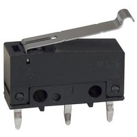
SSG-5L1T
Description
Basic / Snap Action / Limit Switches Hinge Quick Cn #110 .6N OF 5A
Manufacturer
Omron
Specifications of SSG-5L1T
Operating Force
61 gf
Contact Form
SPDT
Contact Rating
5 Amps
Actuator
Lever, Hinge
Termination Style
Quick Connect
Contact Configuration
SPDT
Microswitch Type
Snap Action
Actuation Type
Lever
Contact Voltage Ac Nom
250V
Contact Voltage Dc Nom
250V
Contact Current Max
5A
Switch Terminals
Solder
Actuator Style
Lever
Operating Force Max
0.6N
Rohs Compliant
Yes
Lead Free Status / RoHS Status
Lead free / RoHS Compliant
Lead Free Status / RoHS Status
Lead free / RoHS Compliant, Lead free / RoHS Compliant


SSG
Specifications
1. General Ratings
Note: 1. The values in the parentheses are for the SSG-01.
2. TÜV Rheinland Approved Rating (EN61058-1/IEC1058-1)
SSG-5 series:
SSG-01 series: 0.1 A at 30 VDC (T125, 50,000 operations)
3. UL, CSA Approved Rating
SSG-5 series:
SSG-01 series: 0.1 A at 125 VAC, 0.1 A at 30 VDC (6,000 operations)
96
125 VAC
250 VAC
8 VDC
14 VDC
30 VDC
125 VDC
250 VDC
Operating speed
Operating frequency
Insulation resistance
Contact resistance
Dielectric strength
Inrush current
Vibration resistance
Shock resistance
Life expectancy
Degree of protection (IP code)
Degree of protection against
electrical shock
Proof tracking index
Switch category (IEC335-1)
Ratings
Characteristics
Rated voltage
2. The above current ratings are the values of the steady-state current.
3. Inductive load has a power factor of 0.7 min. (AC) and a time constant of 7 ms max. (DC).
4. Lamp load has an inrush current of 10 times the steady-state current.
5. Motor load has an inrush current of 6 times the steady-state current.
6. If the switch is used in a DC circuit and is subjected to a surge current, connect a surge suppressor across the switch.
5 A at 250 VAC (T125, 50,000 operations)
5 A at 125 VAC, 3 A at 250 VAC (6,000 operations)
5 (0.1) A (see note 1)
3 A
5 A
5 A
4 (0.1) A (see note 1)
0.4 A
0.2 A
NC
Resistive load
0.1 mm to 1 m/s (at pin plunger)
Mechanical: 400 operations/min
Electrical:
100 M min.
OF 1.50 N: SSG-5 series: 30 m max.
OF 0.50 N SSG-5 series: 50 m max.
1,000 VAC, 50/60 Hz for 1 min between contacts of the same polarity
(600 VAC for SSG-01H and SSG-01T series)
1,500 VAC, 50/60 Hz for 1 min between each terminal and ground
1,500 VAC, 50/60 Hz for 1 min between each terminal and non-current-carrying metal part
SSG-5:
SSG–01: NO: 1 A max.
Malfunction: 10 to 2,000 Hz, 196 m/s
Malfunction: 490 m/s
Mechanical: 10,000,000 operations min. (OT: rated value)
Electrical:
IP00 (IEC1058-1)
Class I (IEC1058-1)
175 V (IEC1058-1)
D (IEC1058-1)
Non-inductive load
NO
NO: 20 A max.
NC: 10 A max.
NC: 1 A max.
SSG-01 series:50 m max.
SSG-01 series:100 m max.
200,000 operations min. (5 A at 125 VAC for SSG-5, 0.1 A at 125 VAC for SSG-01,
resistive OT:full)
60 operations/min
1.5 A
1 A
2 A
2 A
2 A
0.05 A
0.03 A
NC
2
(approx. 50G) (Contact open: 10 s max., lever position: at TTP)
Lamp load
0.7 A
0.5 A
NO
2
(20G) (Contact open: 10 s max., lever position: at TTP)
3 A
2 A
5 A
4 A
3 A
0.4 A
0.2 A
NC
Inductive load
NO
Inductive laod
2.5 A
1.5 A
3 A
3 A
3 A
0.05 A
0.05 A
NC
Motor load
1.3 A
0.8 A
NO
SSG
Related parts for SSG-5L1T
Image
Part Number
Description
Manufacturer
Datasheet
Request
R

Part Number:
Description:
Subminiature Basic Switch
Manufacturer:
Omron
Datasheet:
Part Number:
Description:
Subminiature Basic Switch
Manufacturer:
Omron
Datasheet:
Part Number:
Description:
Subminiature Basic Switch
Manufacturer:
Omron
Datasheet:
Part Number:
Description:
SWITCH SUBMINI SPDT 5A PIN PLNGR
Manufacturer:
Omron
Datasheet:

Part Number:
Description:
SWITCH SUBMINI SPDT 5A HINGE LVR
Manufacturer:
Omron
Datasheet:
Part Number:
Description:
SWITCH SUBMINI SPDT 5A PIN PLNGR
Manufacturer:
Omron
Datasheet:
Part Number:
Description:
SWITCH SUBMINI SPDT 5A PIN PLNGR
Manufacturer:
Omron
Datasheet:
Part Number:
Description:
SWITCH SUBMINI SPDT 5A HINGE LVR
Manufacturer:
Omron
Datasheet:
Part Number:
Description:
SWITCH SUBMINI SPDT 5A ROLL LEVR
Manufacturer:
Omron
Datasheet:
Part Number:
Description:
SWITCH SUBMINI SPDT 5A ROLL LEVR
Manufacturer:
Omron
Datasheet:
Part Number:
Description:
Subminiature Basic Switch
Manufacturer:
Omron
Datasheet:
Part Number:
Description:
Subminiature Basic Switch
Manufacturer:
Omron
Datasheet:
Part Number:
Description:
SUBMINIATURE BASIC SWITCH
Manufacturer:
Omron
Datasheet:
Part Number:
Description:
Subminiature Basic Switch
Manufacturer:
Omron
Datasheet:

Part Number:
Description:
Subminiature Basic Switch
Manufacturer:
Omron
Datasheet: