D4B-1116N Omron, D4B-1116N Datasheet - Page 13
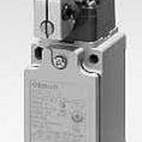
D4B-1116N
Manufacturer Part Number
D4B-1116N
Description
Basic / Snap Action / Limit Switches Adjustable Lever PG13.5 1NC/1NO
Manufacturer
Omron
Specifications of D4B-1116N
Contact Form
NO / NC
Contact Rating
2 Amps
Actuator
Lever, Roller
Operating Force
9.41 N
Termination Style
Screw
Actuation Type
Adjustable Roller Lever
Operating Force Max
960gf
Switch Operation
Snap Action
Contact Voltage Ac Max
600V
Contact Current Ac Max
10A
Switch Terminals
Screw
Svhc
No SVHC (15-Dec-2010)
Lead Free Status / RoHS Status
Lead free / RoHS Compliant
Lead Free Status / RoHS Status
Lead free / RoHS Compliant


D4B-jN
CW, CCW or Two-way Operation
The head of Side Rotary Switches can be converted in seconds to
CW, CCW, or two-way operation. The conversion procedure fol-
lows.
Precautions
If the D4B-jN is applied to an emergency stop circuit or safety cir-
cuit for prevention of injury, use the D4B-jN model that has an NC
contact equipped with a force-separation mechanism, and make
sure that the D4B-jN operates in the positive mode. Furthermore,
secure the D4B-jN with screws or equivalent parts that are tight-
ened in a single direction so that the D4B-jN cannot be easily
removed. Then provide a protection cover for the D4B-jN and post
a warning label near the D4B-jN.
In order to protect the D4B-jN from damage due to short-circuiting,
connect a fuse breaking a current 1.5 to 2 times higher than the
rated current in parallel with the D4B-jN.
Operating Environment
Correct Use
The D4B-jN is for indoor use. The D4B-jN may malfunction if
the D4B-jN is used outdoors. Be sure to use a model with a
lever-type actuator for outdoor use instead.
Do not use the D4B-jN in the following places.
Places with radical temperature changes.
Places with excessive humidity that may cause condensa-
tion.
Places with excessive vibration.
Places where metal dust, oil, or chemical may be sprayed to
the D4B-jN.
Head cover (Push and rotate)
Operating posi-
tion mark (arrow)
Procedure
If an application satisfying EN standards is to employ the D4BL, ap-
ply the 10-A gI or gG fuse approved by IEC269.
Do not apply the D4B-jN to the door without applying a stopper to
the door.
If the D4B-jN is used with the actuator normally pressed, the
D4B-jN may malfunction or may soon have reset failures. Be sure
to check and replace the D4B-jN regularly.
Tightening Torque
Note: Apply a tightening torque of 0.78 to 0.88 N
1 Terminal screw
2 Cover-mounting
3 Head-mounting
4 Switch-mounting
5 Connector
6 Cap screw (for
1. Dismount the head by loosening the four screws that secure
2. Turn over the head to set the desired operation (CW, CCW, or
3. Set the CW hole on the head at the operation position mark
screw
screw
screw (M5)
three-conduit
models)
it.
both). The desired operation can be selected by setting the
mode selector knob shown in the figure. This knob is factory
set to the “CW + CCW” (two-way operation) position.
(arrow) for clockwise operation or set the CCW hole right at
the arrow for counterclockwise operation. In either case, be
sure to set the hole position exactly at the arrow point.
Since loose screws may
cause a malfunction,
tighten each screw to the
appropriate torque.
9 kgf cm} to conduit models.
Type
0.59 to 0.78 N m {6 to 8 kgf cm}
1.18 to 1.37 N m {12 to 14 kgf cm}
0.78 to 0.98 N m {8 to 10 kgf cm}
4.90 to 5.88 N m {50 to 60 kgf cm}
1.77 to 2.16 N m {18 to 22 kgf cm}
1.27 to 1.67 N m {13 to 17 kgf cm}
Proper tightening torque
(4)
(3)
(1)
(5)
(2)
D4B-jN
m {8 to
13
Related parts for D4B-1116N
Image
Part Number
Description
Manufacturer
Datasheet
Request
R

Part Number:
Description:
LSW,PG13.5,SNAP,TOP PLNGR
Manufacturer:
Omron
Datasheet:

Part Number:
Description:
Safety Limit Switch
Manufacturer:
Omron
Datasheet:

Part Number:
Description:
SWITCHES
Manufacturer:
Omron
Datasheet:

Part Number:
Description:
LIMIT SWITCH ADJ ROLL LEVER
Manufacturer:
Omron
Datasheet:

Part Number:
Description:
G6S-2GLow Signal Relay
Manufacturer:
Omron Corporation
Datasheet:
Part Number:
Description:
Compact, Low-cost, SSR Switching 5 to 20 A
Manufacturer:
Omron Corporation
Datasheet:
Part Number:
Description:
Manufacturer:
Omron Corporation
Datasheet: